Passive Components Blog
No Result
View All Result
  • Home
  • NewsFilter
    • All
    • Aerospace & Defence
    • Antenna
    • Applications
    • Automotive
    • Capacitors
    • Circuit Protection Devices
    • electro-mechanical news
    • Filters
    • Fuses
    • Inductors
    • Industrial
    • Integrated Passives
    • inter-connect news
    • Market & Supply Chain
    • Market Insights
    • Medical
    • Modelling and Simulation
    • New Materials & Supply
    • New Technologies
    • Non-linear Passives
    • Oscillators
    • Passive Sensors News
    • Resistors
    • RF & Microwave
    • Telecommunication
    • Weekly Digest

    Samsung Electro-Mechanics High Capacitance MLCCs for ADAS SoCs

    Murata Expands its Automotive Common Mode Choke Coils to 150C and High Current Capability

    Bourns Releases New Current Transformer

    Skeleton Releases GrapheneGPU to Reduce AI Energy Consumption by 44% and Boosts Power by 40%

    VINATech Expands Aluminum Capacitor Portfolio with Acquisition of Enesol

    binder Offers Wide Range of M12 Panel Mount Connectors

    Bourns Releases New Shielded Power Inductors for DDR5

    Supercapacitors Benefits in Industrial Valve Fail-Safe Control Systems

    Wk 21 Electronics Supply Chain Digest

    Trending Tags

    • Ripple Current
    • RF
    • Leakage Current
    • Tantalum vs Ceramic
    • Snubber
    • Low ESR
    • Feedthrough
    • Derating
    • Dielectric Constant
    • New Products
    • Market Reports
  • VideoFilter
    • All
    • Antenna videos
    • Capacitor videos
    • Circuit Protection Video
    • Filter videos
    • Fuse videos
    • Inductor videos
    • Inter-Connect Video
    • Non-linear passives videos
    • Oscillator videos
    • Passive sensors videos
    • Resistor videos

    Coupled Inductors Circuit Model and Examples of its Applications

    Inductor Resonances and its Impact to EMI

    Highly Reliable Flex Rigid PCBs, Würth Elektronik Webinar

    Causes of Oscillations in Flyback Converters

    How to design a 60W Flyback Transformer

    Modeling and Simulation of Leakage Inductance

    Power Inductor Considerations for AI High Power Computing – Vishay Video

    Coupled Inductors in Multiphase Boost Converters

    VPG Demonstrates Precision Resistor in Cryogenic Conditions

    Trending Tags

    • Capacitors explained
    • Inductors explained
    • Resistors explained
    • Filters explained
    • Application Video Guidelines
    • EMC
    • New Products
    • Ripple Current
    • Simulation
    • Tantalum vs Ceramic
  • Knowledge Blog
  • Suppliers
    • Who is Who
  • Events
No Result
View All Result
Passive Components Blog
No Result
View All Result

How to Choose the Right Inductor for DC-DC Buck Applications

2.5.2025
Reading Time: 5 mins read
A A

DC-DC converters of different varieties are widely used in markets such as telecommunications, automotive, medical (portable), and industrial.

The ‘buck’ DC-DC converter is employed to step voltages down without isolation and utilizes an inductor as an energy storage element. This article will explain how to choose the right Inductor for DC-DC Buck applications, its calculation of impedance and ripple current to get optimum performance.

RelatedPosts

TDK Releases Hybrid Polymer Aluminum Capacitors with Enhanced Ripple Current Capability

Selection Guide for DC-Link Film Capacitors in Automotive Electric Compressors; KEMET App Note

Tantalum Polymer use in GaN based applications

A simplified buck converter schematic can be observed in Figure 1. The output voltage of this converter is always lower than the input voltage.

When S1 is open, the energy stored in the inductor sustains the current through the load through D1 with C1 also discharging into the load. S1 switches at high frequency and the duty cycle of switching defines the output voltage.

When S1 is closed, the DC input voltage is applied to the output filter inductor L1 and current flows through the inductor into the output capacitor C1 and to the load.

Simplified buck schematic
Figure 1. Simplified buck schematic

When selecting an inductor for a buck converter the following parameters need to be defined:

  • Maximum input voltage = Vin max
  • Minimum input voltage = Vin min
  • Maximum output current = Iout max
  • Operating frequency = f
  • Output voltage = Vout
  • Minimum output current = Iout min

So, for example, with f = 500 kHz, Vo = 5 volts, Iout max = 4 amps, Iout min = 0.5 amps, Vin max = 13.5 volts (car battery) and Vin min = 8.5 volts.

You can select what the inductor ripple current is – it sets output ripple voltage across the ESR of C1.

For this example, the inductor current stays continuous at the minimum specified load. So, the minimum of the ripple current just touches zero at minimum load, as seen in Figure 2. This makes control loop compensation a lot simpler. The inductor current stays continuous at any load, even with high ripple current, if D1 is a synchronous rectifier MOSFET. Though high ripple current does generate higher core losses.

Calculations

Since the operating frequency is 500 kHz,

Find the minimum duty ratio, Dmin

Find the required inductance value, L

DC-DC Buck converter inductor calculation

Find the delta current (ripple current), ∆I

Find the peak current, I pk

Find the RMS current, I rms

DC-DC Buck converter inductor ripple current calculation
Typical inductor ripple current
Figure 2. Typical inductor ripple current

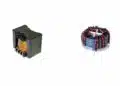
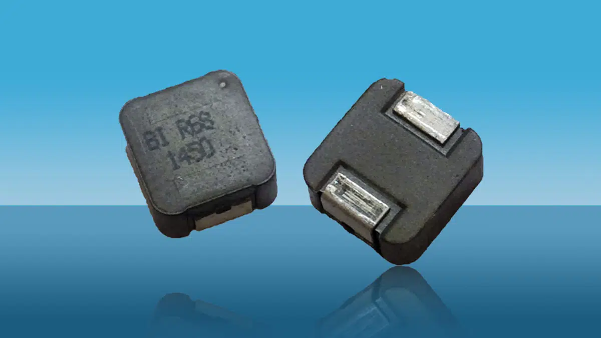
An optimum inductor can be chosen using TT Electronics (TT) inductor datasheets. In this example, TT part number HA72L-06308R2LFTR is suggested, which is automotive grade, -55 ºC to +155 ºC (AEC-Q200 certified) with the electrical parameters below:

TT p/nL @ 0 ampDCR typicalDCR maxI rmsI dc (sat) 30% Roll offTypical picture
HA72L-06308R2LFTR8.2 µH64 mΩ68 mΩ4.0 amps gives about 40 ºC Temp Rise7.5 amps
Table 1. Data sheet specification for TT part HA72L-06308R2LFTR
HA72L-06308R2LF DC bias and Temp rise
Figure 3. DC-DC Buck converter Inductor DC bias and Temp rise example

Figure 3 shows the inductance roll-off is 100 = 6.1% at 4.42 amps DC, which is close to the required value of 7.56 µH with a temperature rise of less than 40 °C.

The temperature rise in the data sheet graph is for DC current. In the example, there is also AC ripple current. A more precise temperature rise calculation, including ohmic and AC loss effects in the core and wire, is beyond the scope of this article but would be dependent on the below parameters:

  1. Skin depth at the operating frequency
  2. Surface area of the inductor
  3. Wire resistance at the operating temperature
  4. AC flux density, BAC, calculated from peak current, inductance, core cross sectional area and number of turns

TT Electronics has provided numerous solutions to the medical, automotive, and various industrial sectors. They provide semi and full custom designs to meet your critical specifications.

featured image source: TT Electronics

Related

Source: TT Electronics

Recent Posts

Murata Expands its Automotive Common Mode Choke Coils to 150C and High Current Capability

29.5.2025
8

Bourns Releases New Current Transformer

29.5.2025
11

Bourns Releases New Shielded Power Inductors for DDR5

29.5.2025
22

Samsung Electro-Mechanics Releases 165C Automotive 0806 Size Power Inductors

21.5.2025
30

Coupled Inductors Circuit Model and Examples of its Applications

21.5.2025
74

Würth Elektronik Introduces LTspice Models for ESD Products

21.5.2025
45

Littelfuse Gate Driver Integrates Diode and Current Limit Resistor in Compact IC

21.5.2025
21

Capacitor Ripple Current Testing: A Design Consideration

21.5.2025
67

TDK Releases 0201 High-Frequency Smallest Inductors

20.5.2025
34

Coilcraft Extends Air Core RF Inductors

20.5.2025
18

Upcoming Events

Jun 4
11:00 - 12:00 CEST

Würth Elektronik PCB Production in Asia

View Calendar

Popular Posts

  • Buck Converter Design and Calculation

    0 shares
    Share 0 Tweet 0
  • Boost Converter Design and Calculation

    0 shares
    Share 0 Tweet 0
  • SEPIC Converter Design and Calculation

    0 shares
    Share 0 Tweet 0
  • Flyback Converter Design and Calculation

    0 shares
    Share 0 Tweet 0
  • LLC Resonant Converter Design and Calculation

    0 shares
    Share 0 Tweet 0
  • Dual Active Bridge (DAB) Topology Explained

    0 shares
    Share 0 Tweet 0
  • Flying Capacitors Explained

    0 shares
    Share 0 Tweet 0
  • Capacitor Symbols

    0 shares
    Share 0 Tweet 0
  • What is a Dielectric Constant and DF of Plastic Materials?

    4 shares
    Share 4 Tweet 0
  • Guide to Snubber Capacitors

    0 shares
    Share 0 Tweet 0

Newsletter Subscription


Passive Components Blog

© EPCI - Leading Passive Components Educational and Information Site

  • Home
  • Privacy Policy
  • EPCI Membership & Advertisement
  • About

No Result
View All Result
  • Home
  • Knowledge Blog
  • Premium Suppliers

© EPCI - Leading Passive Components Educational and Information Site

This website uses cookies. By continuing to use this website you are giving consent to cookies being used. Visit our Privacy and Cookie Policy.
Go to mobile version