This article provides overview of common and less common inductor and transformer symbols.
The inductors, coils or chokes are electrical passive components that have a certain number of turns of wire that introduce magnetic inductance to an electrical circuit to produce a magnetic flux or to mechanically react to magnetic flux variations.
There are many types of inductors available depending to its core type, leads, shileding, number of windings, variability etc. See overview of most often used fixed and variable inductor and transformer symbols.
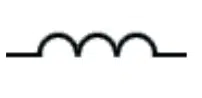
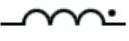
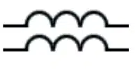
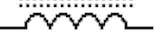
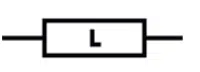
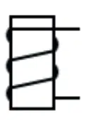
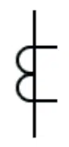
Inductors / Coils / Chokes / Inductance


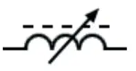
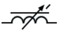
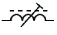
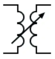
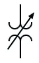
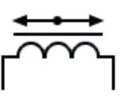
Variable & Adjustable Inductors

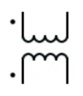
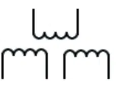
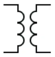
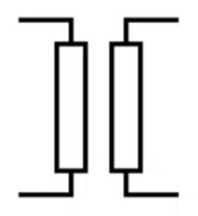
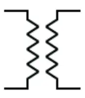
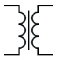
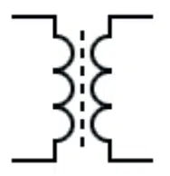
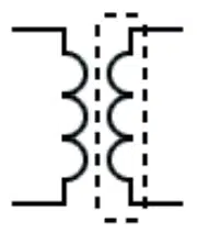
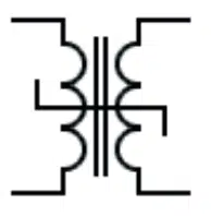
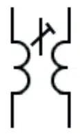
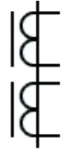
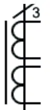
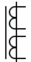
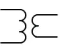
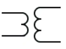
Transformers
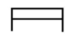
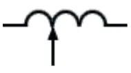
General Symbol
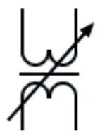
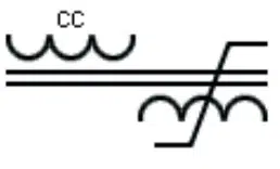
with Continuous Current
Regulation Symbol
Transformer with Voltage
Regulation Symbol
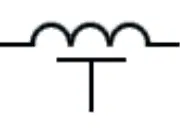
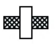
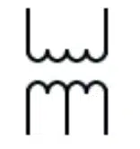
Magnet Symbol
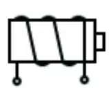
Core Symbol
Symbol
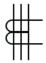
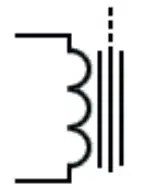
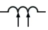
Three Primary Conductors Symbol
Two Secondary Windings
Single Core and 3 Primary
2 Secondary Windings
on a Core
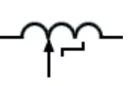
with a Shunt Winding Symbol