Passive Components Blog
No Result
View All Result
  • Home
  • NewsFilter
    • All
    • Aerospace & Defence
    • Antenna
    • Applications
    • Automotive
    • Capacitors
    • Circuit Protection Devices
    • electro-mechanical news
    • Filters
    • Fuses
    • Inductors
    • Industrial
    • Integrated Passives
    • inter-connect news
    • Market & Supply Chain
    • Market Insights
    • Medical
    • Modelling and Simulation
    • New Materials & Supply
    • New Technologies
    • Non-linear Passives
    • Oscillators
    • Passive Sensors News
    • Resistors
    • RF & Microwave
    • Telecommunication
    • Weekly Digest

    Binder Hybrid Connector Simplifies One Cable Automation

    Tapped Inductor Buck Converter Fundamentals

    TAIYO YUDEN Releases Mini Metal Power Inductors

    Molecular Memristor Shows Record 145 kH Emergent Inductance

    Planar vs Conventional Transformer: When it Make Sense

    Researchers Propose Next‑Gen Compact Memory Using Ultra-thin Ferroelectric Capacitors

    Nichicon ADN Automotive Hybrid Aluminum Capacitors Now Available in EMEA

    Wk 19 Electronics Supply Chain Digest

    Electrocaloric Multilayer Capacitors: Towards Quiet, Solid‑State Cooling Around Room Temperature

    Trending Tags

    • Ripple Current
    • RF
    • Leakage Current
    • Tantalum vs Ceramic
    • Snubber
    • Low ESR
    • Feedthrough
    • Derating
    • Dielectric Constant
    • New Products
    • Market Reports
  • VideoFilter
    • All
    • Antenna videos
    • Capacitor videos
    • Circuit Protection Video
    • Filter videos
    • Fuse videos
    • Inductor videos
    • Inter-Connect Video
    • Non-linear passives videos
    • Oscillator videos
    • Passive sensors videos
    • Resistor videos

    Tapped Inductor Buck Converter Fundamentals

    Planar vs Conventional Transformer: When it Make Sense

    Modeling Fringing Field Losses in Inductors & Transformers

    Why Power Inductors Use a Ferrite Core With an Air Gap

    Transformer-Based Power-Line Harvester Magnetic Design

    Thermal Modeling of Magnetics

    Standard vs Planar LLC transformers Comparison for Battery Chargers

    How Modern Tools Model Magnetic Components for Power Electronics

    Advanced Loss Modeling for Planar Magnetics in the Frenetic Planar Tool

    Trending Tags

    • Capacitors explained
    • Inductors explained
    • Resistors explained
    • Filters explained
    • Application Video Guidelines
    • EMC
    • New Products
    • Ripple Current
    • Simulation
    • Tantalum vs Ceramic
  • Knowledge Blog
  • DossiersNew
  • Suppliers
    • Who is Who
  • PCNS
    • PCNS 2025
    • PCNS 2023
    • PCNS 2021
    • PCNS 2019
    • PCNS 2017
  • Events
No Result
View All Result
Passive Components Blog
No Result
View All Result

Mounting Considerations of Radial Crown SMD Aluminum Electrolytic Capacitors in Automotive Power Systems; Kemet Application Note

31.5.2021
Reading Time: 4 mins read
A A

1. A Primer on Aluminum Electrolytic Capacitors

The development of the electrolytic capacitor (e-cap) has been one of the main factors in the successful miniaturization and increased performance of many modern-day electronics. The basic e-cap construction is shown in the figure below:

Figure 1: Power Inverter with DC-Link Caps

Since capacitance is a function of surface area, aluminum foils are first etched to create a rough contour with maximal contact area, resulting in high capacitance and optimal CV-value.

RelatedPosts

Tantalum Capacitor History

Understanding the Influence of ESR and Ripple Current for the Capacitor Selection

Resonant OBC Capacitors

A second foil layer and a paper separator are added to fully complete the capacitor structure, producing an excellent terminal contact with this electrolyte. This aluminum-electrolyte-paper sandwich is then rolled or “wound” into a can and sealed with two terminals.

2. Aluminum Electrolytic Capacitors in Low Voltage Automotive Systems

2.1 DC-Link Capacitors

DC-link capacitors are used to provide a stable DC-voltage, limiting voltage fluctuations even under high ripple current loads, -fluctuations created by the inverter. The DC-link capacitors are acting as a local energy source, connected to the DC- board-net – close to the power electronics (–> low impedance).

Figure 2: Power Inverter with DC-Link Caps

Key requirements, for automotive DC-link capacitors:

  • Ripple current capability
  • Low ESR
  • High-temperature capability
  • Low thermal resistance (…especially when mounted heat-sinked to metallic chassis)
  • Operational life
  • Low impedance
  • Low inductance
  • High reliability

2.2 48V Automotive Systems and Applications

The increasing electrical power demand in modern cars is the primary cause for introducing the 48V board net. Major automotive OEMs will fully migrate to 48V mild hybrid solutions within a few years, in addition to offering plug-in hybrid electric vehicles (PHEVs) and electric vehicles (EVs). Reduced CO2 emissions and improved fuel consumption are the key drivers for this evolution.

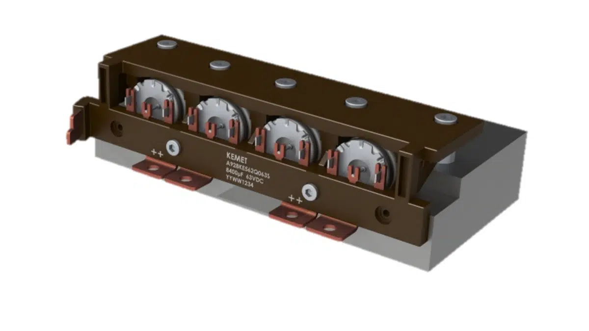
Mild hybrid systems are typically designed for 10-30 kW charging power. A maximum 40kW peak output power can be confirmed on projects today, showing full compatibility with future 48V drives. This creates a need for a DC-link capacitor module, corresponding to 3-6 axial electrolytic capacitors, connected in parallel, using well-known Axial Aluminum wet technology and considering the Axial Hybrid for high power versions trend. Typically, the capacitors are heatsinked to the metallic chassis to achieve max ripple current capability.

Figure 3: A927/8 Capacitor Module

2.3 Mounting to a Heatsink

Robust mounting to the heatsink results in excellent heat transfer (low thermal resistance), lower capacitor bank temperature (extended operational life), and significantly improved ripple current capability. At the same time, excellent mechanical robustness and vibration resistance is achieved.

Figure 4: Heatsink for Capacitor Module
Figure 5: Capacitor Module Mounted on Heatsink

The application chassis (metallic) can preferably be adapted for heatsinking the module. The chassis/ heatsink can be either air-cooled or water-cooled. Thermal paste or thermal pad should be used to ensure low thermal resistance and optimal heat transfer.

3.   Electrical Characterization

The following electrical characterization was performed on a 63V 5600μF module measuring 135mm x 52mm x 31mm, part number: A928KE562Q063.

Figure 7: Impedance vs. Frequency
Figure 8: Inductance vs. Frequency
Figure 9: ESR vs. Frequency

Related

Source: Kemet

Recent Posts

Tapped Inductor Buck Converter Fundamentals

13.5.2026
11

Molecular Memristor Shows Record 145 kH Emergent Inductance

12.5.2026
11

Planar vs Conventional Transformer: When it Make Sense

11.5.2026
36

Researchers Propose Next‑Gen Compact Memory Using Ultra-thin Ferroelectric Capacitors

11.5.2026
28

Nichicon ADN Automotive Hybrid Aluminum Capacitors Now Available in EMEA

11.5.2026
23

Electrocaloric Multilayer Capacitors: Towards Quiet, Solid‑State Cooling Around Room Temperature

7.5.2026
186

KYOCERA 10 µF 0201 MLCC Brings High‑Capacitance into Mobile Designs

6.5.2026
54

Würth Elektronik Introduces Compact Flat-wire SMT Power Inductors for Automotive

5.5.2026
50

KYOCERA AVX Extends MLV Varistors for 48V Automotive Protection

5.5.2026
27

Upcoming Events

May 19
16:00 - 17:00 CEST

Designing Qi2 Wireless Power Systems: Practical Development and EMC Optimization

Jun 2
16:00 - 17:00 CEST

Calculation, Simulation and Measurement of 800V EMC Filters

Jun 16
16:00 - 17:00 CEST

EMC with EMC – EMC‑compliant design with electromechanical connectors

View Calendar

Popular Posts

  • Buck Converter Design and Calculation

    0 shares
    Share 0 Tweet 0
  • Boost Converter Design and Calculation

    0 shares
    Share 0 Tweet 0
  • Flyback Converter Design and Calculation

    0 shares
    Share 0 Tweet 0
  • LLC Resonant Converter Design and Calculation

    0 shares
    Share 0 Tweet 0
  • MLCC and Ceramic Capacitors

    0 shares
    Share 0 Tweet 0
  • Dual Active Bridge (DAB) Topology

    0 shares
    Share 0 Tweet 0
  • Capacitor Charging and Discharging

    0 shares
    Share 0 Tweet 0
  • What Electronics Engineer Needs to Know About Passive Low Pass Filters

    0 shares
    Share 0 Tweet 0
  • Ripple Current and its Effects on the Performance of Capacitors

    3 shares
    Share 3 Tweet 0
  • MLCC Case Sizes Standards Explained

    0 shares
    Share 0 Tweet 0

Newsletter Subscription


Passive Components Blog

© EPCI - Leading Passive Components Educational and Information Site

  • Home
  • Privacy Policy
  • EPCI Membership & Advertisement
  • About

No Result
View All Result
  • Home
  • Knowledge Blog
  • PCNS

© EPCI - Leading Passive Components Educational and Information Site

This website uses cookies. By continuing to use this website you are giving consent to cookies being used. Visit our Privacy and Cookie Policy.
Go to mobile version