


Samsung Electro-Mechanics has introduced a family of low ESL multilayer ceramic capacitors (MLCCs) targeting high-performance automotive ADAS SoCs where power integrity and high‑frequency noise suppression are critical.
These Samsung reverse-geometry and 3‑terminal MLCC capacitors aim to reduce the number of decoupling capacitors around advanced SoCs while addressing tight PCB space constraints in automotive ECUs.
Key features and benefits
- Low ESL structures for improved high-frequency decoupling
The lineup combines reverse-geometry “LICC” MLCCs and 3‑terminal (3T) MLCCs, both designed to lower equivalent series inductance compared to standard two-terminal capacitors of the same case size. This helps maintain stable supply rails at GHz-range switching and edge rates typical of advanced ADAS SoCs. - Optimized for high-performance ADAS SoCs
The capacitors are aimed at SoC power rail decoupling in systems processing data from multiple cameras, LiDAR and radar sensors, where higher core currents and faster transients demand better high-frequency power delivery and noise suppression. - Reduced capacitor count and PCB area
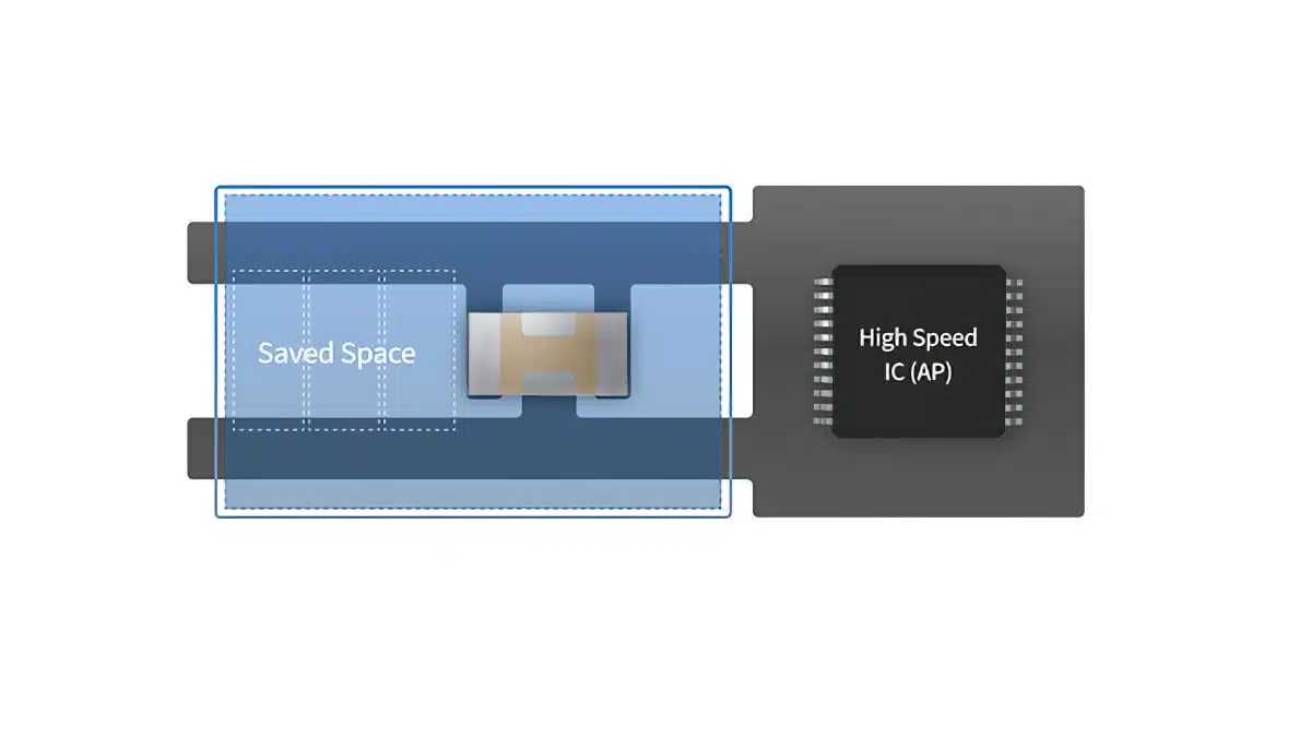
By providing better impedance at high frequencies, a single low ESL MLCC can replace multiple standard MLCCs placed in parallel, reducing component count, routing complexity and overall PCB footprint around the SoC. - Automotive-grade X7T dielectric
All listed parts use an X7T dielectric, providing a wide operating temperature range and controlled capacitance characteristics suitable for automotive environments, while still delivering high capacitance in very compact case sizes. - Miniaturized case sizes down to 0402/1005 and 0204/0510
The 3T low ESL MLCCs are available in 0402 (1005 metric) and 0603 (1608 metric) sizes, while reverse-geometry low ESL types use a 0204 (0510 metric) format that effectively swaps length and width to reduce ESL without enlarging the footprint. - Mass production and samples for key part numbers
Several 1 µF and 2.2 µF parts are in mass production, while higher capacitance 4.3 µF and 10 µF options are currently available as samples, giving engineers a clear migration path as designs evolve.
Low ESL MLCC line-up overview
The press release presents a concise table of both reverse-geometry and 3T low ESL MLCCs, covering capacitance from 1 µF to 10 µF with rated voltages from 2.5 V to 16 V.
Reverse-geometry low ESL MLCCs (LICC)
Reverse-geometry capacitors swap the long and short dimensions of a standard chip, which shortens the current path between the terminals and directly lowers ESL. This approach is often called LICC (low inductance chip capacitor) and is particularly effective when used very close to SoC power pins.
Reverse-geometry low ESL parts (0204 / 0510 metric)
| Part number | Capacitance | Rated voltage | Dielectric | Size (inch/metric) | L (mm) | W (mm) | T (mm) | Status |
|---|---|---|---|---|---|---|---|---|
| CLL5Z225MS21PN | 2.2 µF | 2.5 Vdc | X7T | 0204 / 0510 | 0.65 +0.05 / −0.10 | 1.15 +0.05 / −0.10 | 0.20 ±0.02 | Mass production |
| CLL5Z105MR41PN | 1 µF | 4 Vdc | X7T | 0204 / 0510 | 0.58 ±0.10 | 1.10 ±0.10 | 0.43 ±0.10 | Mass production |
| CLL5Z105MS21PN | 1 µF | 2.5 Vdc | X7T | 0204 / 0510 | 0.65 +0.05 / −0.10 | 1.15 +0.05 / −0.10 | 0.20 ±0.02 | Mass production |
In practice, the reverse geometry allows you to stay within a very small footprint while gaining a lower inductive path, which is helpful when decoupling core rails or high-speed I/O supplies placed tightly around the SoC package.
3-terminal low ESL MLCCs (3T)
3‑terminal MLCCs integrate a dedicated feedthrough structure with separate input and output terminals, effectively creating a local decoupling path that can significantly reduce high-frequency noise and impedance. They are especially useful when routing constraints limit via and plane options near the SoC.
3‑terminal low ESL parts (0402 / 0603)
| Part number | Capacitance | Rated voltage | Dielectric | Size (inch/metric) | L (mm) | W (mm) | T (mm) | Status |
|---|---|---|---|---|---|---|---|---|
| CL05Z105MR41PT | 1 µF | 4 Vdc | X7T | 0402 / 1005 | 1.00 ±0.20 | 0.50 ±0.20 | 0.40 ±0.10 | Mass production |
| CL10Z105MO66PT | 1 µF | 16 Vdc | X7T | 0603 / 1608 | 1.60 ±0.10 | 0.80 ±0.10 | 0.60 ±0.10 | Mass production |
| CL05Z435MS41PT | 4.3 µF | 2.5 Vdc | X7T | 0402 / 1005 | 1.00 ±0.20 | 0.50 ±0.20 | 0.40 ±0.10 | Sample available |
| CL10Z106MRF6PT | 10 µF | 4 Vdc | X7T | 0603 / 1608 | 1.60 ±0.20 | 0.80 ±0.20 | 1.25 ±0.10 | Sample available |
With these 3T devices, engineers can achieve both high capacitance and low ESL in familiar 0402 and 0603 footprints, simplifying adoption in existing library and footprint schemes.
Typical applications
Samsung positions these low ESL MLCCs primarily for ADAS SoC power and high-speed digital rails, but the same benefits extend to many other automotive and high-speed digital use cases.
- High-performance ADAS SoCs
Used as high-frequency decoupling directly at the SoC core, GPU or AI accelerator rails, reducing voltage droop and switching noise in systems processing camera, radar and LiDAR data. - High-speed serial interfaces and SerDes
Applied on supply pins of high-speed links, where low ESL decoupling helps maintain signal integrity and reduces jitter caused by supply noise. - Automotive domain controllers and central compute units
Suitable for high-current digital supplies in zonal controllers or central ECUs that consolidate multiple ADAS and infotainment functions. - Power management ICs (PMIC) and point-of-load regulators
Placed at PMIC outputs feeding critical digital rails, where a combination of bulk capacitance and low ESL improves transient response. - Space-constrained automotive ECUs
Beneficial in small form factor ECUs where board space, especially around the SoC package, is limited and routing options are constrained.
Technical highlights
This section summarizes key technical parameters and what they mean in practice for design engineers.
Capacitance and voltage ratings
- Capacitance range:
The current lineup covers capacitances of 1 µF, 2.2 µF, 4.3 µF and 10 µF, which are typical values for high-frequency decoupling close to SoCs and high-speed ICs. - Voltage range:
Rated voltages include 2.5 Vdc, 4 Vdc and 16 Vdc. Lower voltage parts address core rails around 0.8–1.2 V with adequate derating, while 16 V options can be used on intermediate rails or I/O supplies with suitable design margins. - Dielectric and temperature characteristics:
The X7T classification indicates a ceramic dielectric optimized for automotive conditions with defined capacitance stability over temperature and voltage, suitable for ADAS environments where temperatures can vary significantly.
Package sizes and dimensions
- Reverse-geometry 0204 / 0510 format
The longer dimension across the terminations helps reduce ESL compared to a conventional chip of similar footprint area, which is advantageous when placed directly adjacent to SoC power pins. - 3T 0402 / 1005 and 0603 / 1608
These standard case sizes simplify PCB library integration and allow designers to use low ESL solutions without changing overall layout constraints. - Low profile options
Some reverse-geometry parts offer thickness around 0.20 mm, which can be advantageous in compact, stacked or module-based assemblies where overall z‑height is limited.
Product status and roadmap
- Mass production parts
Several 1 µF and 2.2 µF parts are already in mass production, which is important for automotive projects facing long validation cycles and requiring stable supply. - Sample-available higher capacitance parts
4.3 µF and 10 µF 3T low ESL MLCCs are currently sample-available, indicating that higher capacitance options are entering the pipeline and can be evaluated in current designs according to manufacturer datasheets.
Design-in notes for engineers
When designing ADAS ECUs and SoC boards with these low ESL MLCCs, a few practical points can help maximize their benefit.
- Place as close as possible to SoC power pins
The reduced ESL is most effective when the capacitor sits physically close to the pin it decouples, with short traces or vias and minimal loop area. Prioritize placement over routing convenience where possible. - Combine low ESL MLCCs with bulk capacitance
Use these reverse-geometry or 3T MLCCs in parallel with larger bulk capacitors (for example, standard MLCCs or polymer capacitors) to cover both high-frequency and mid-frequency impedance requirements on each rail. - Pay attention to voltage derating
Rated voltages down to 2.5 V require careful derating for core rails under automotive transients and cold cranking. Always consult the manufacturer’s voltage and temperature derating recommendations to avoid excessive field stress. - Evaluate impedance profiles with PDN analysis tools
Use power distribution network (PDN) simulation tools to compare the impedance of standard versus low ESL MLCC combinations. This allows you to quantify how many standard capacitors can be replaced by a single reverse-geometry or 3T device. - Consider 3T parts where routing is constrained
3‑terminal MLCCs can be particularly effective in BGA escape regions or tightly routed SoC perimeters where via and plane access is limited. Their structure can provide a low-inductance path even when layout options are restricted. - Plan for supply chain and second sourcing
Since these are specialized low ESL MLCCs, discuss availability and long-term supply with your distributor or directly with Samsung Electro-Mechanics early in the project lifecycle, and check if form-fit-function alternatives exist or can be qualified. - Leverage sample-available high-capacitance 3T devices early
For future-proofing designs, consider evaluating the 4.3 µF and 10 µF 3T parts already at sample stage so that their footprints and placement can be reserved on current PCB spins according to manufacturer datasheets.
Source
This article is based on an official product news release from Samsung Electro-Mechanics describing their low ESL MLCC solutions for high-performance ADAS SoCs, complemented by the detailed information available on the corresponding product pages and datasheets provided by the manufacturer.


