


Würth Elektronik publishes AppNote with tips for designing SEPIC converters using coupled and uncoupled inductors.
Würth Elektronik addresses the operation of a Single-Ended Primary-Inductor-Converter (SEPIC) in both continuous and discontinuous conduction modes (CCM and DCM). The 28-page document also includes design considerations and guidelines with focus on the power magnetics.
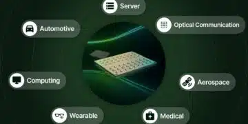
The SEPIC is a non-isolated switching power supply topology generating an output voltage that can be higher, equal or lower than the input voltage. Typical applications include battery-powered devices and chargers, automotive power systems, photovoltaic converters, LED lighting, and power factor correction stages.
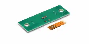
This new Application Note from Würth Elektronik provides a detailed analysis of the SEPIC converter with particular emphasis on the implementation with a coupled inductor, such as the WE-MCRI. It also includes an analysis of “ripple current steering” technique and the key role that the leakage inductance plays in the converter, all supported by SPICE simulations and measurements on a real DC-DC SEPIC converter prototype.
Coupled or uncoupled
Unlike topologies with a single inductor, such as buck, boost or buck-boost converters, the SEPIC power stage requires two inductors. These can be implemented as uncoupled, separate inductors, or alternatively configured as a coupled power inductor with two windings on a common core. This configuration not only reduces the number of components but also requires less inductance to generate the same ripple current amplitude compared to a solution with uncoupled inductors. Moreover, the magnetic coupling of the windings enables the implementation of “ripple current steering”. This is a technique in which the ripple current of the input winding can be “steered” to the output winding, helping to reduce conducted EMI noise. “When designing a SEPIC with coupled inductors, it is important to understand the influence of the coupling factor on the converter performance. In contrast to typical scenarios, a higher leakage inductance can be of advantage in this case,” explains Eleazar Falco, Senior Application Engineer at Würth Elektronik eiSos and author.
Introduction
The SEPIC can produce an output voltage higher or lower than the input, maintaining the same polarity. This makes it valuable in systems with fluctuating supply or load conditions, such as photovoltaic converters, automotive electronics, LED drivers, and battery chargers.
The note discusses:
- CCM and DCM operation
- Component selection and calculation
- Influence of inductor coupling, leakage inductance, and ripple current steering
- Simulation and real measurement data from prototype hardware
Key Points
- Topology Basics: SEPIC combines boost-like input current (continuous) and buck-boost-like output (discontinuous), connected via an AC coupling capacitor (CAC).
- Coupled vs. Uncoupled Inductors: Coupling can reduce ripple current by up to 50% and enable ripple steering to reduce EMI.
- Operating Modes: Analysis covers Continuous Conduction Mode (CCM), Boundary mode, and Discontinuous Conduction Mode (DCM).
- Design Equations: Provided for inductors, capacitors, switches, duty cycle, and current/voltage stresses.
- Ripple Current Steering: Intentional imbalance in winding turns, leakage inductance, or volt-seconds can shift ripple from one winding to the other, reducing EMI filter requirements.
- Leakage Inductance: Often considered a parasitic, but here shown as beneficial for ripple steering tolerance.
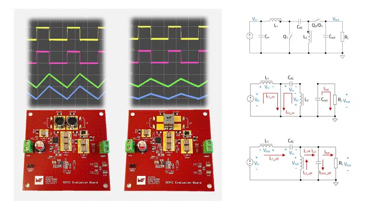
- Measurements & Validation: SPICE simulations closely matched to experimental results on real boards.
Extended Summary
SEPIC Principle of Operation
The document explains how a SEPIC converter works — a type of DC‑DC converter that can step voltage up or down without changing polarity. It’s often used in electronics like car systems, solar converters, LED lighting, and battery chargers. The note compares two design styles:
- Using two separate inductors
- Using a coupled inductor (two windings on one magnetic core)
It also covers how to choose components, the differences between operating in continuous vs discontinuous conduction modes, and how to use ripple current steering to cut down on electromagnetic interference (EMI).
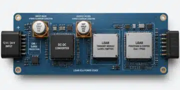
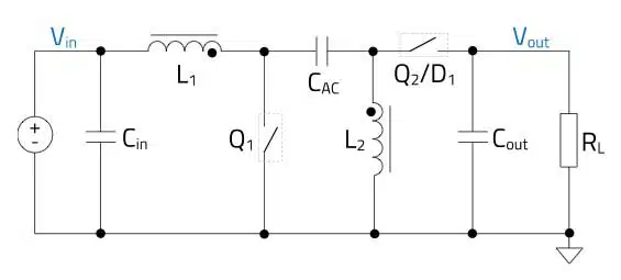
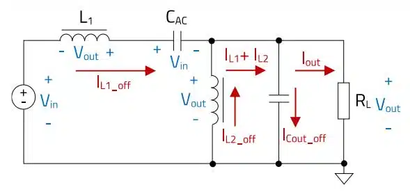
The SEPIC power stage (Fig. 1) uses two inductors (L1, L2), AC coupling capacitor (CAC), output capacitor (Cout), control transistor (Q1), and diode or synchronous switch (Q2/D1). The AC capacitor blocks DC transfer while allowing AC energy transfer, also providing inherent output short-circuit protection.
Key Takeaways
- How it works: SEPIC transfers energy through an AC‑coupling capacitor between two inductor stages.
- Two inductors or one core: Coupling windings can shrink ripple currents and allow EMI‑reducing tricks.
- Two main modes:
- CCM (Continuous Conduction Mode): Inductor currents never drop to zero.
- DCM (Discontinuous Conduction Mode): Inductor currents hit zero part of the cycle, more common at light load.
- Ripple current steering: Deliberately shifting current ripple from one winding to the other can reduce EMI filtering needs.
- Leakage inductance: Normally unwanted, but here it can improve tolerance to design imbalances.
How the SEPIC Operates
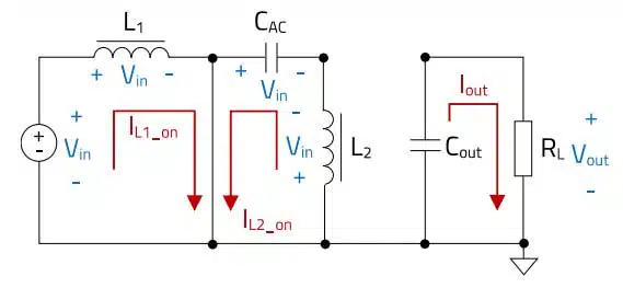
- On phase (switch closed): Both inductors store energy; load is fed by the output capacitor.
- Off phase (switch open): Inductors release energy through the coupling capacitor to the load.
- The average voltage‑time across each inductor balances out over a switching cycle.
Coupled vs. Uncoupled Inductors
- Separate inductors: Simpler, easier to source, but higher ripple currents.
- Coupled inductors: Can halve ripple amplitude for the same inductance; make ripple steering possible.
Ripple Current Steering
By tweaking:
- Turns ratio between windings
- Leakage inductance
- Volt‑second applied per winding
you can redirect most ripple to one side, reducing it on the input side and easing EMI filter design.
Why Leakage Can Help
A bit of leakage inductance makes ripple steering less sensitive to part‑to‑part variations, so performance stays more consistent in real‑world builds.
Conclusion
The SEPIC is a flexible voltage converter. Coupled inductors and ripple steering can improve efficiency, cut costs, and reduce EMI filters — especially in custom, higher‑power designs. For smaller projects, the benefit might not outweigh the added complexity.
Download the full application note in pdf from Würth Elektronik website: ANP135
Further read: