Passive Components Blog
No Result
View All Result
  • Home
  • NewsFilter
    • All
    • Aerospace & Defence
    • Antenna
    • Applications
    • Automotive
    • Capacitors
    • Circuit Protection Devices
    • electro-mechanical news
    • Filters
    • Fuses
    • Inductors
    • Industrial
    • Integrated Passives
    • inter-connect news
    • Market & Supply Chain
    • Market Insights
    • Medical
    • Modelling and Simulation
    • New Materials & Supply
    • New Technologies
    • Non-linear Passives
    • Oscillators
    • Passive Sensors News
    • Resistors
    • RF & Microwave
    • Telecommunication
    • Weekly Digest

    Samsung Electro-Mechanics Focuses MLCCs on AI servers and Automotive

    Modelithics Library Expands with 120 New Models

    Understanding Inductor Dot Markings and Their Application in LTspice

    Exxelia Offers High-Q RF Microwave Capacitors for High Reliability Applications

    Premo Releases PLC Transformer for EV and Smart Grid Applications

    Wk 29 Electronics Supply Chain Digest

    June 2025 ECST Components Survey Delivers Stunning Results

    Rubycon Extends Capacitance of Polymer Hybrid Aluminum Capacitors

    VINATech Partner with ONiO to Develop Batteryless IoT Power Architecture

    Trending Tags

    • Ripple Current
    • RF
    • Leakage Current
    • Tantalum vs Ceramic
    • Snubber
    • Low ESR
    • Feedthrough
    • Derating
    • Dielectric Constant
    • New Products
    • Market Reports
  • VideoFilter
    • All
    • Antenna videos
    • Capacitor videos
    • Circuit Protection Video
    • Filter videos
    • Fuse videos
    • Inductor videos
    • Inter-Connect Video
    • Non-linear passives videos
    • Oscillator videos
    • Passive sensors videos
    • Resistor videos

    Understanding Inductor Dot Markings and Their Application in LTspice

    Accelerating Full Bridge LLC Resonant Converter Design with Frenetic AI

    Understanding Switched Capacitor Converters

    Coupled Inductors Circuit Model and Examples of its Applications

    Inductor Resonances and its Impact to EMI

    Highly Reliable Flex Rigid PCBs, Würth Elektronik Webinar

    Causes of Oscillations in Flyback Converters

    How to design a 60W Flyback Transformer

    Modeling and Simulation of Leakage Inductance

    Trending Tags

    • Capacitors explained
    • Inductors explained
    • Resistors explained
    • Filters explained
    • Application Video Guidelines
    • EMC
    • New Products
    • Ripple Current
    • Simulation
    • Tantalum vs Ceramic
  • Knowledge Blog
  • Suppliers
    • Who is Who
  • Events
No Result
View All Result
Passive Components Blog
No Result
View All Result

TDK Unveils New Family of eco-friendly SMD Varistors

18.12.2024
Reading Time: 3 mins read
A A

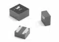
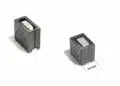
TDK Corporation announces the release of five new eco-friendly SMD multilayer varistors (MLVs). 

As an industry first, these components feature a reduced carbon (CO2) footprint while fulfilling demanding automotive qualification requirements.

RelatedPosts

TDK Introduces High Current 80VDC Board-Mount EMI Filters

TDK Increases Current Ratings of Automotive Thin-Film Power Inductors

TDK Releases Industry First 1uF 100V X7R MLCCs in 1608 Case

These parts are the first representatives of TDK’s new X-series, which is continually being expanded for automotive as well as for industrial and consumer applications. The X series satisfies both the growing demand for eco-friendly products, and the commercial requirement for cost-attractive products, while maintaining TDK’s high level of reliability and performance.

The first five parts are automotive qualified according to AEC-Q200, a feature which can be recognized by a “1” following the “X” in the part number. They are generally used to protect a vehicle’s engine management system, electronic control units (ECUs), airbags, ABS, ESP, etc. against transient overvoltages on the battery lines resulting from events such as load dump and jump start.

These components provide ESD protection up to 30 kV according to IEC 61000-4-2 and comply with automotive pulses according to ISO 7637-2/16750-2.

Available in four EIA package sizes (0603, 0805, 1206, and 1210), the new components support maximum RMS operating voltages of 14 V, 25 V, and 30 V respectively, with response times to voltage transients ranging from 10 ps to 500 ps. They handle surge currents from 5 A to 400 A for 8/20 µs pulses, while maintaining a leakage current of just 1 µA to 25 µA at the rated DC voltage and room temperature. Their operating temperature spans from -55 °C to +150 °C without derating, even at higher temperatures.

The X-series is being further expanded to a comprehensive range of overvoltage protection components, also for industrial and consumer applications. Simulation models for PSpice are available.

Features

  • Reliable ESD protection up to 30 kV according to IEC 61000-4-2
  • Comply with automotive pulses according to ISO 7637-2/16750-2
  • Load-dump and jump-start protection
  • Low leakage current
  • Qualified based on AEC-Q200 (X1-Series)
  • No temperature derating up to +125 °C (X1-series up to +150 °C)
  • High lifetime robustness
  • Stable protection level

 Applications

Transient overvoltage protection for:

  • Automotive battery lines
  • Engine management systems
  • Electronic control units (ECUs)
  • Airbag, ABS, ESP, etc
Ordering CodeMaximum RMS operating 
voltage VRMS [V]
Varistor voltage VV 
(1 mA, +25 °C)
Maximum surge current
 Isurge,max [A] (8/20 μs)
Dimensions 
(L x W x H) [mm]
B72500X1250L0602551.9 … 70.151.6 x 0.8 x 0.9
B72510X1140S1621422.0 … 27.01202.0 x 1.25 x 1.4
B72520X1300K0623042.3 … 51.72003.2 x 1.6 x 1.7
B72530X1140S1621422.0 … 27.04003.2 x 2.5 x 1.7
B72530X1250K0622535.1 … 42.93003.2 x 2.5 x 1.7

Related

Source: TDK

Recent Posts

Samsung Electro-Mechanics Focuses MLCCs on AI servers and Automotive

22.7.2025
9

Exxelia Offers High-Q RF Microwave Capacitors for High Reliability Applications

21.7.2025
19

Premo Releases PLC Transformer for EV and Smart Grid Applications

21.7.2025
7

Rubycon Extends Capacitance of Polymer Hybrid Aluminum Capacitors

16.7.2025
63

Knowles Releases Inductors for Mission-Critical RF Applications

15.7.2025
27

Bourns Unveils Smallest Automotive Grade Thick Film Resistors

14.7.2025
26

Bourns Increases Maximum Inductance Values of Semi-Shielded Power Inductors

11.7.2025
12

YAGEO Unveils Next Gen BMS Isolation Transformers

10.7.2025
22

Littelfuse Compact Tactile Switch Offers Low-Noise Switching and Dust Protection

10.7.2025
13

Bourns Releases SMD Chip High-Power Metal Strip Current Sense Resistors in 2010 Case

10.7.2025
11

Upcoming Events

Jul 23
13:00 - 14:00 CEST

PCB design for a Smartwatch

Jul 23
17:00 - 17:40 CEST

Could Piezoelectric Devices replace Magnetics in Power Converters?

Jul 29
16:00 - 17:00 CEST

Impact of Elevated Voltage and Temperature on Molded Power Inductors in DC/DC converters

View Calendar

Popular Posts

  • Buck Converter Design and Calculation

    0 shares
    Share 0 Tweet 0
  • Boost Converter Design and Calculation

    0 shares
    Share 0 Tweet 0
  • Flyback Converter Design and Calculation

    0 shares
    Share 0 Tweet 0
  • LLC Resonant Converter Design and Calculation

    0 shares
    Share 0 Tweet 0
  • What is a Dielectric Constant and DF of Plastic Materials?

    4 shares
    Share 4 Tweet 0
  • Dual Active Bridge (DAB) Topology Explained

    0 shares
    Share 0 Tweet 0
  • Ripple Current and its Effects on the Performance of Capacitors

    3 shares
    Share 3 Tweet 0
  • How to Design an Inductor

    0 shares
    Share 0 Tweet 0
  • MLCC Case Sizes Standards Explained

    0 shares
    Share 0 Tweet 0
  • MLCC and Ceramic Capacitors

    0 shares
    Share 0 Tweet 0

Newsletter Subscription


Passive Components Blog

© EPCI - Leading Passive Components Educational and Information Site

  • Home
  • Privacy Policy
  • EPCI Membership & Advertisement
  • About

No Result
View All Result
  • Home
  • Knowledge Blog
  • Premium Suppliers

© EPCI - Leading Passive Components Educational and Information Site

This website uses cookies. By continuing to use this website you are giving consent to cookies being used. Visit our Privacy and Cookie Policy.
Go to mobile version