


This presentation from Würth Elektronik by Antwi Nimo and Markus Haepe explains IEC 61558 safety standard related to transformers and how these are reflected in the transformer designs.
Introduction
Transformer safety is critical in the design of power electronics and SMPS (Switch-Mode Power Supply) units, governed by rigorous international standards. IEC 61558 sets the global requirements for transformer insulation, creepage, clearance distances, and safety testing. This presentation summarizes its most updated aspects, practical implementation, and harmonization with other standards.
Key Takeaways
- Würth Elektronik’s presentation highlights safety standards for transformers, focusing on IEC 61558 and its implementation.
- IEC 61558 mandates transformer safety requirements like insulation levels and partial discharge testing.
- Designers must consider mechanical, environmental, thermal, and electrical factors for optimal transformer safety.
- Partial discharge testing is now essential for transformers exceeding 750V using specific insulation techniques.
- Achieving compliance with IEC 61558 requires advanced insulation strategies and robust testing practices.
1. Transformer Safety Standards—Scope and Definitions
1.1 IEC 61558 Overview: Scope & Structure
IEC 61558 is the main global safety standard for transformers, ensuring proper isolation and reliability across consumer, industrial, medical, AV/ICT, and laboratory applications. This standard supplements product-centric standards, providing technical requirements for core construction, insulation systems, and verification testing.
| Standard | Application Area | Highlights |
|---|---|---|
| IEC 61558 | General transformers | Isolation, creepage/clearance, insulation levels |
| IEC 61558-2-16 | SMPS transformers | High frequency, partial discharge, reinforced insulation |
| IEC 62368 | AV/ICT | Functional insulation, device safety |
| IEC 60601 | Medical | Risk management, patient safety |
| IEC 61010 | Lab/measurement | Testing, indication devices |
1.2 Insulation Levels and Design Impact
- Functional Insulation: For operational reliability only, not intended for shock protection
- Basic Insulation: Guards against electric shock under normal conditions
- Supplementary Insulation: Backup protection if basic insulation fails
- Double Insulation: Combination of basic and supplementary, providing two independent protective layers
- Reinforced Insulation: Equivalent to double, achieved with a single sophisticated system
| Insulation Level | Wire Structure Example |
|---|---|
| Basic | Copper core, single insulation layer |
| Supplementary | Copper core, double insulation layers (e.g., white + blue enamel) |
| Reinforced | Copper core, three insulation layers or FIW (Fully Insulated Wire) |
Advances, such as FIW, let designers achieve reinforced levels without bulky multi-layer winding and special tape systems.
2. Core Technical Safety Factors
2.1 Mechanical, Environmental, Thermal, and Electrical Factors
- Mechanical: Bobbin material (e.g. plastic, ceramic), margin/shave tape, winding geometry, and connection terminals directly affect spacing and isolation.
- Environmental: Application placement (indoors, cleanroom, outdoor) dictates pollution degree; higher pollution requires longer distances and robust insulation.
- Thermal: High energy density/small design challenges associated with effective cooling, risk of thermal aging of insulation.
- Electrical: Maximum voltage, expected current, overvoltage category, and working voltage set requirements for clearance and creepage.
2.2 Overvoltage Categories & Pollution Degrees
| Overvoltage Category | Typical Location | Isolation Requirement |
|---|---|---|
| IV | Main fuse box, utility entry | Highest surge withstand, longest creepage/clearance |
| III | Distribution, switch panels | High protection |
| II | Plug-in equipment | Standard protection |
| I | Handheld/electronics | Minimal protection |
Pollution degree refers to environmental contaminants: Degree 1 is clean (laboratory), Degree 2 is office, Degree 3 is industrial, Degree 4 is harsh/outdoor.
2.3 Clearance & Creepage—Equations and Practice
Clearance: Shortest air distance between conductive parts for a given voltage
Creepage: Path along an insulation surface between conductors, subject to surface tracking
| Voltage (V) | Basic Creepage (mm) | Reinforced Creepage (mm) |
|---|---|---|
| 265 | 5 | 8 |
| 400 | 7 | 10 |
| 500 | 8 | 12 |
Creepage = f(Uworking, PD, MG, FR)
Where Uworking = working voltage, PD = pollution degree, MG = material group, FR = frequency ratio.
3. Transformer Construction & Testing
3.1 Practical Insulation Solutions
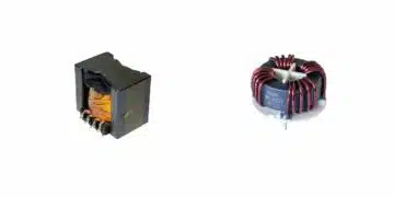
- Winding Options:
– Standard enamelled wire
– FIW (Fully Insulated Wire): enables reinforced insulation with reduced space
– Triple insulated wire: three independent insulation layers - Bobbins & Coil Formers: Use of engineered plastics, margin or shave tape, multi-section bobbin designs to optimize creepage/clearance.
- Potting & Encapsulation: Application of resin or gel can lower pollution degree, reducing insulation distance requirements.
– Encapsulated windings allow for more compact high-voltage transformers.
3.2 Partial Discharge Test Requirements
- IEC 61558 now mandates partial discharge testing for:
- All transformers using FIW or triple-insulated wire above 750V working voltage
- Some other reinforced insulation designs
- Testing methods must include measurement of discharge at voltages per VDE guidance.
- Partial discharge identifies defects in insulation before catastrophic failure.
Clearance and creepage are now often calculated with the rated supply voltage rather than just working voltage.
Overvoltage categories and frequency dependence have been clarified and added key design requirements.
3.3 Approval & Harmonization
- IEC 61558 insulation strategies are adaptable to IEC 62368 (for AV/ICT), but specific approval may require additional component and wire certification under UL rules.
- Always consult with your approval laboratory for latest harmonization requirements, as FIW and tape-insulated designs have different approval paths in global standards.
4. Harmonization with Other Standards
4.1 IEC 62368 Compatibility
IEC 61558 insulation levels, creepage/clearance requirements, and partial discharge testing are mostly compatible with IEC 62368 for AV/ICT. However, specifics for UL/CSA—especially with wire grades and construction—require additional review with approval bodies.
Conclusion
IEC 61558 is the keystone for transformer safety, especially as power density and miniaturization challenge older design norms. Achieving compliance relies on multilayered insulation strategies, precise mechanical layouts, and robust testing—principally partial discharge validation. Emerging requirements, such as harmonized overvoltage categories and pollution degrees for encapsulated or potted constructions, are changing both design and approval pathways for modern power transformers.
FAQ Transformer Safety
IEC 61558 is an international safety standard that defines insulation, clearance, creepage, and testing requirements for transformers. Compliance ensures electrical safety, reduces risk of breakdown, and harmonizes transformer design with global standards.
The standard outlines functional, basic, supplementary, double, and reinforced insulation. Each provides increasing levels of protection against electrical shock and fault conditions.
Overvoltage categories (I-IV) represent environment severity. Category IV is the most demanding, requiring greater insulation distances. Correct category selection is fundamental for transformer reliability.
Partial discharge testing detects insulation weaknesses before catastrophic failure. IEC 61558 requires it for all transformers using FIW or triple-insulated wire above 750V, or reinforced constructions.
Yes. With adequate creepage/clearance and proper margin tape or tubing, conventional enamelled wire designs can achieve basic and reinforced insulation. Approval depends on correct distance and layering.
How-to: Achieve IEC 61558 Compliance in Transformer Design
- Define Application and Environmental Category
Decide transformer usage (e.g. SMPS, medical, AV/ICT) and determine overvoltage and pollution degree. Input these as parameters for design calculations.
- Select Appropriate Insulation Level
Choose from functional, basic, double, or reinforced insulation—guided by risk scenario and required safety margins.
- Design Windings and Select Wire Type
ick standard enamelled wire, FIW, or triple-insulated wire. Apply appropriate winding structure and tape, ensuring required creepage and clearance distances are met.
- Dimension and Verify Creepage & Clearance
Use calculation tools and standards tables (example: 400V requires ≥7mm for basic insulation). Confirm all physical distances comply with IEC minimums.
- Perform Partial Discharge Testing
Test for insulation flaws. For transformers above 750V or using reinforced insulation, conduct and record partial discharge results as per IEC and VDE methods.
- Prepare Documentation for Approval
Compile all test records, calculation sheets, material certifications, and construction details. Present to regulatory authority or test lab for formal approval.