


This presentation from Würth Elektronik by Andreas Nadle provides an in-depth walkthrough for designing, simulating, and validating 3-phase EMI filters based on real EMC signatures of a device under test (DUT).
Introduction
3-phase AC/DC power conversion is fundamental to modern industrial applications, yet it comes with challenges—particularly electromagnetic interference (EMI) that can degrade system performance and regulatory compliance.
This presentation provides a comprehensive guide to designing, simulating, and validating 3-phase input EMI / EMC filters using state-of-the-art digital tools and real measurement data. Designed for engineers and technical specialists, the article distills essential steps from interference basics through component selection to laboratory validation.
The design of 3-phase EMI filters—filtering both common-mode (CM) and differential-mode (DM) interference—requires a systematic approach that combines theoretical analysis, simulation, and experimental validation.
Key Takeaways
- This article provides a comprehensive guide for designing, simulating, and validating 3-phase EMI filters.
- Key topics include the origins of noise, component selection, and optimization for regulatory compliance.
- It emphasizes the importance of using X and Y capacitors for differential and common mode noise suppression.
- Engineers can utilize digital tools and real measurement data to ensure robust performance.
- The presentation includes practical steps for filter design, testing, and layout considerations.
Chapter 1: Basics of Interference in 3-Phase Systems
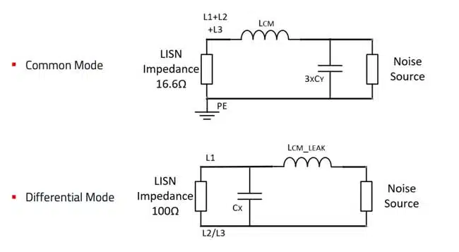
1.1 Differential Mode vs Common Mode Currents
– Differential Mode (DM): Currents follow intended circuit paths, are easier to trace, and generally higher amplitude.
– Common Mode (CM): Currents flow via parasitic paths, affecting unintended circuit segments and are a major source of radiated EMI.
| Mode | Path | Current magnitude | Filtering | Main cause |
|---|---|---|---|---|
| Differential | Within circuit | High | LC, π, T Topology | dI/dt (current switching) |
| Common | Parasitic/earth | Low (µA) | CMC, Y-capacitors | dU/dt (voltage surges) |
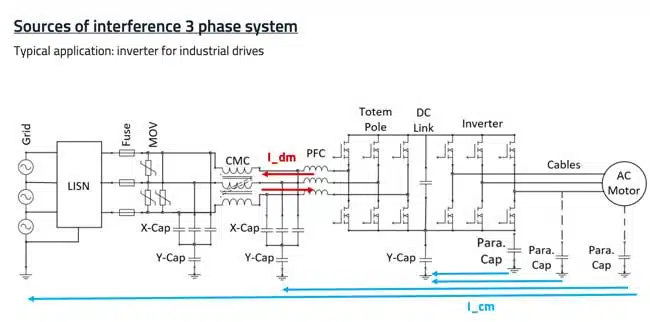
1.2 Application Example: Industrial Drives
Inverters for industrial drives are prime examples, with high switching frequencies and power levels that exacerbate EMI concerns.
Chapter 2: Filter Components and Selection
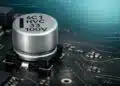
2.1 Safety Capacitors: Y2, X2, MLCC, and Film
Safety capacitors reduce EMI by providing paths for high-frequency currents. Their classification (X2, Y2) dictates voltage, failure mode, and use location.
- X Capacitors: Connected between phases (line-to-line). They suppress differential mode (DM) noise. X1 capacitors are rated for higher surge voltages (up to 5 kV), while X2 capacitors are smaller and cheaper but limited to 2.5 kV surges.
- Y Capacitors: Connected between phase and protective earth. They suppress common mode (CM) noise. Their value is limited by leakage current regulations (typically < 4.7 nF per line in industrial systems).
| Type | Application | Advantages | Limitations |
|---|---|---|---|
| X Capacitors | Phase-to-phase filtering | High surge capability | Larger size, higher cost |
| Y Capacitors | Phase-to-earth filtering | Excellent high-frequency suppression | Leakage current limitations |
Engineers must balance capacitance value, safety ratings, and leakage current. Film capacitors are robust but bulky, while MLCCs (multi-layer ceramic capacitors) offer excellent high-frequency performance but limited capacitance.
- Y2 Capacitors (Phase-to-Protective Earth):
- WCAP-FTY2: Pitch 10–37.5mm, 330VAC, 1nF–1µF, -40°C/+110°C
- WCAP-CSSA (MLCC Y2): SMD 1808–2220, 250VAC, 33pF–4.7nF, -55°C/+125°C
- X2 Capacitors (Phase-to-Phase):
- WCAP-FTX2/FTXX: Pitch 7.5–37.5mm, 310VAC/275VAC, 5.6nF–6.8µF, -40°C/+105°C
- WCAP-FTXH: Pitch 15–37.5mm, 310VAC, 33nF–10µF, up to +110°C, THB 1000h @ 85°C 85%
| Type | Key Series | Volt. (Vrms) | Capacitance Range | Temp. Range |
|---|---|---|---|---|
| Y2 – Film/MLCC | WCAP-FTY2, WCAP-CSSA | 250–330 | 33pF–1µF | -55 to +125°C |
| X2 – Film/MLCC | WCAP-FTX2, FTXH | 275–310 | 5.6nF–10µF | -40 to +110°C |
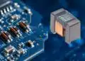
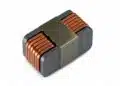
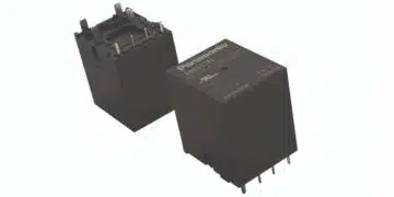
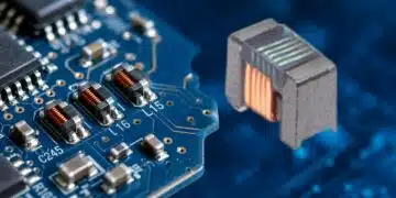
2.2 Common Mode Chokes (CMCs)
Common mode chokes (CMCs) provide inductance to attenuate CM currents. Their performance depends on core material:
| Core Material | Frequency Range | Advantages | Limitations |
|---|---|---|---|
| Manganese-Zinc Ferrite | Up to ~5 MHz | Good low-frequency attenuation | Limited high-frequency performance |
| Nickel-Zinc Ferrite | 5–30 MHz | Better high-frequency suppression | Lower permeability at low frequencies |
| Nanocrystalline | Broadband (kHz–tens of MHz) | Excellent wideband performance | Higher cost, sensitive to saturation |
Note: Real inductance depends on test frequency; nanocrystalline cores show substantial drop-off above 100kHz.
- MnZn ferrite core: 1–24A, 0.52mH–12mH, 1kHz–2MHz frequency range (e.g., WE-TPB, Ø47mm)
- Nanocrystalline core: 20–46A, up to 208mH, 1kHz–20MHz (e.g., WE-TPBHV, Ø70mm)
- Frequency Response: Nanocrystalline offers better performance above 1MHz, but with core nonlinearity and specific derating at higher frequencies.
| Core Material | Current (A) | Inductance (mH) | Freq. Range (kHz) | Example Series |
|---|---|---|---|---|
| MnZn | to 24 | 0.52-12 | 1–2000 | WE-TPB |
| Nanocrystalline | to 46 | 0.2–208 | 1–20000 | WE-TPBHV |
2.3 Surge Protection Varistors
Varistors protect against voltage surges. Selection is based on voltage class, current capacity, certified reliability.
- WE-VD Series: 5–20mm diameter, 14V–1000V RMS, 100A–10,000A, -40°C to +105°C, certified by UL/IEC/VDE.
2.4 Component Selection Example: Lab Device Under Test (DUT)
- Filter for 4kW inverter drive, 5A, 400V 3-phase grid
- Combination: Y2 MLCC caps, X2 film caps, nanocrystalline CMC, WE-VD varistor
Chapter 3: Filter Topology, Calculation and Simulation
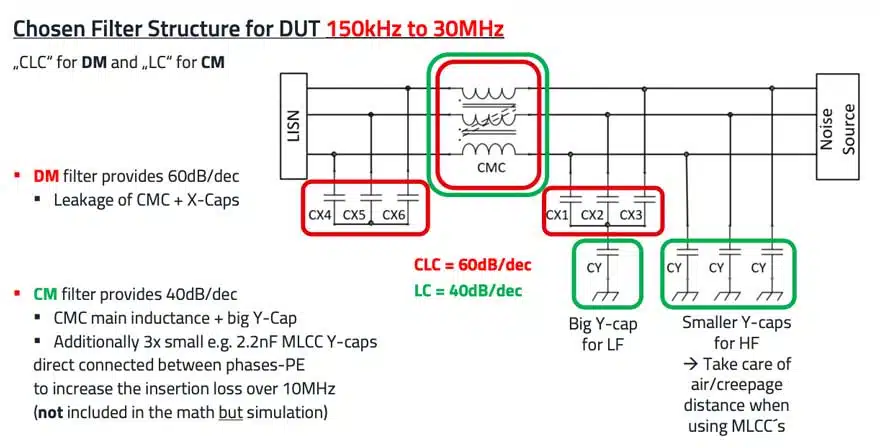
3.1 Detailed Filter Structures
CM and DM Filtering Structure:
- CM (Common Mode): LC topology (CMC + large Y-capacitor)
- DM (Differential Mode): CLC π topology (3 x X2 between each phase, 2 x series CMCs)
- High-frequency suppression: 3x small MLCC Y2-caps between each phase and PE supplement the main Y-cap
| Functional Block | Main Parts | Purpose |
|---|---|---|
| CM Filter | CMC + large Y-cap | Suppress parasitic return-path currents |
| DM Filter | X2 film caps + series CMCs | Smooth line-to-line switching noise |
| Surge Protection | Varistor (WE-VD) | Clamp surges, protect filter/downgrid |
3.2 Component Sizing and Calculations
Key variables:
– fc = corner frequency
– Ldm, Lcm = DM/CM inductance
– Cx, Cy = interphase and PE capacitance
– Required attenuation = 60dB at 200kHz as specified by CISPR B
Effective X2 Capacitance (Cx) Between Phases:
Effective Y2 Capacitance (Cy), phase-to-PE:
Corner Frequency (DM or CM):