Passive Components Blog
No Result
View All Result
  • Home
  • NewsFilter
    • All
    • Aerospace & Defence
    • Antenna
    • Applications
    • Automotive
    • Capacitors
    • Circuit Protection Devices
    • electro-mechanical news
    • Filters
    • Fuses
    • Inductors
    • Industrial
    • Integrated Passives
    • inter-connect news
    • Market & Supply Chain
    • Market Insights
    • Medical
    • Modelling and Simulation
    • New Materials & Supply
    • New Technologies
    • Non-linear Passives
    • Oscillators
    • Passive Sensors News
    • Resistors
    • RF & Microwave
    • Telecommunication
    • Weekly Digest

    Bourns Extends Rotational Life Option for its Guitar Potentiometer

    Modeling and Simulation of Leakage Inductance

    Power Inductor Considerations for AI High Power Computing – Vishay Video

    TAIYO YUDEN Releases Compact SMD Power Inductors for Automotive Application

    Fischer Releases High Vibration Robust Ratchet Locking USB-C Connector System

    Littelfuse Unveils High-Use Tactile Switches with 2 Million Cycle Lifespan

    KYOCERA AVX Releases Compact High-Directivity Couplers

    Supercapacitors Emerge as a Promising Solution to AI-Induced Power Energy Spikes

    Wk 18 Electronics Supply Chain Digest

    Trending Tags

    • Ripple Current
    • RF
    • Leakage Current
    • Tantalum vs Ceramic
    • Snubber
    • Low ESR
    • Feedthrough
    • Derating
    • Dielectric Constant
    • New Products
    • Market Reports
  • VideoFilter
    • All
    • Antenna videos
    • Capacitor videos
    • Circuit Protection Video
    • Filter videos
    • Fuse videos
    • Inductor videos
    • Inter-Connect Video
    • Non-linear passives videos
    • Oscillator videos
    • Passive sensors videos
    • Resistor videos

    Modeling and Simulation of Leakage Inductance

    Power Inductor Considerations for AI High Power Computing – Vishay Video

    Coupled Inductors in Multiphase Boost Converters

    VPG Demonstrates Precision Resistor in Cryogenic Conditions

    Comparison Testing of Chip Resistor Technologies Under High Vibration

    EMC Challenges for High Speed Signal Immunity and Low EMI

    MOSFET Gate Drive Resistors Power Losses

    Modified Magnetic Reluctance Equivalent Circuit and its Implications

    Improving Common Mode Noise Reduction while Decreasing BOM

    Trending Tags

    • Capacitors explained
    • Inductors explained
    • Resistors explained
    • Filters explained
    • Application Video Guidelines
    • EMC
    • New Products
    • Ripple Current
    • Simulation
    • Tantalum vs Ceramic
  • Knowledge Blog
  • Suppliers
    • Who is Who
  • Events
No Result
View All Result
Passive Components Blog
No Result
View All Result

What is a Capacitor ?

22.1.2025
Reading Time: 9 mins read
A A

This article explains very basic definition of What is a Capacitor ?, its main application and technologies.

Capacitor Definition

Capacitors are passive electrical components to store electric energy

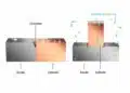
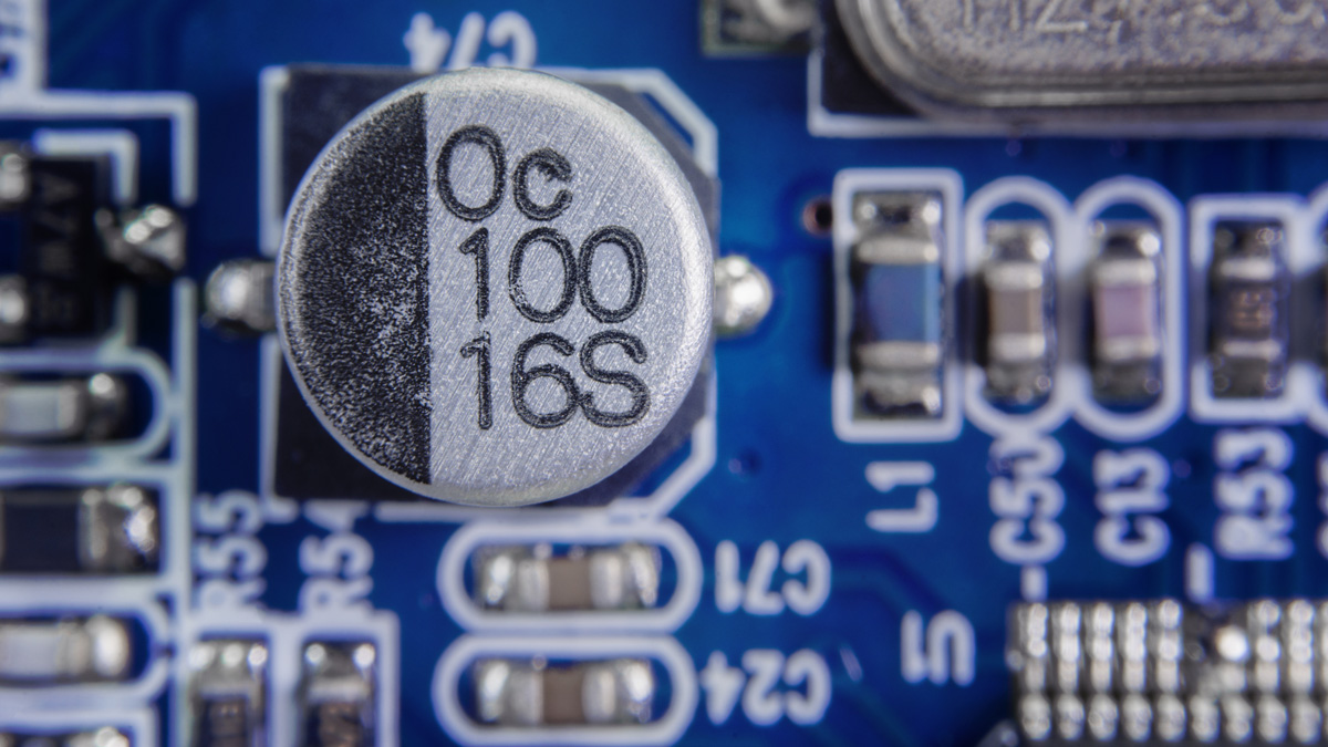
A capacitor is made from electrical conductive electrodes that are separated by an insulator. The insulating layer is called a dielectric. Although all capacitors share the same basic principle components, the material choice, configurations and features can vary widely.

RelatedPosts

Capacitor Charging Losses Explained

Supercapacitor Balancing Methods Comparison

Failure Analysis of Capacitors and Inductors

Overview of common capacitors symbols can be find in related article here.

A capacitor is able to store energy in an electrostatic field that is generated by a potential difference across the conducting electrodes. So when an electrode is subject to a voltage, one plate of the capacitor will collect positive charge while the other will be negatively charged. The ratio of this electric charge and the potential difference (voltage) is called the capacitance and it is expressed in farads. The leaking current through the dielectric is called the leakage current.

Capacitor Technologies

There are wide capacitor technologies that differ in features, behaviour, range of electrical parameters covered. The most common capacitor technologies include:

  • Air/Vacuum
  • Aluminum
  • Ceramic
  • Film
  • Tantalum and Niobium
  • Silicon
  • Supercapacitors
Fig. 2. The most common mass volume capacitor technologies capacitance vs voltage range; source: EPCI

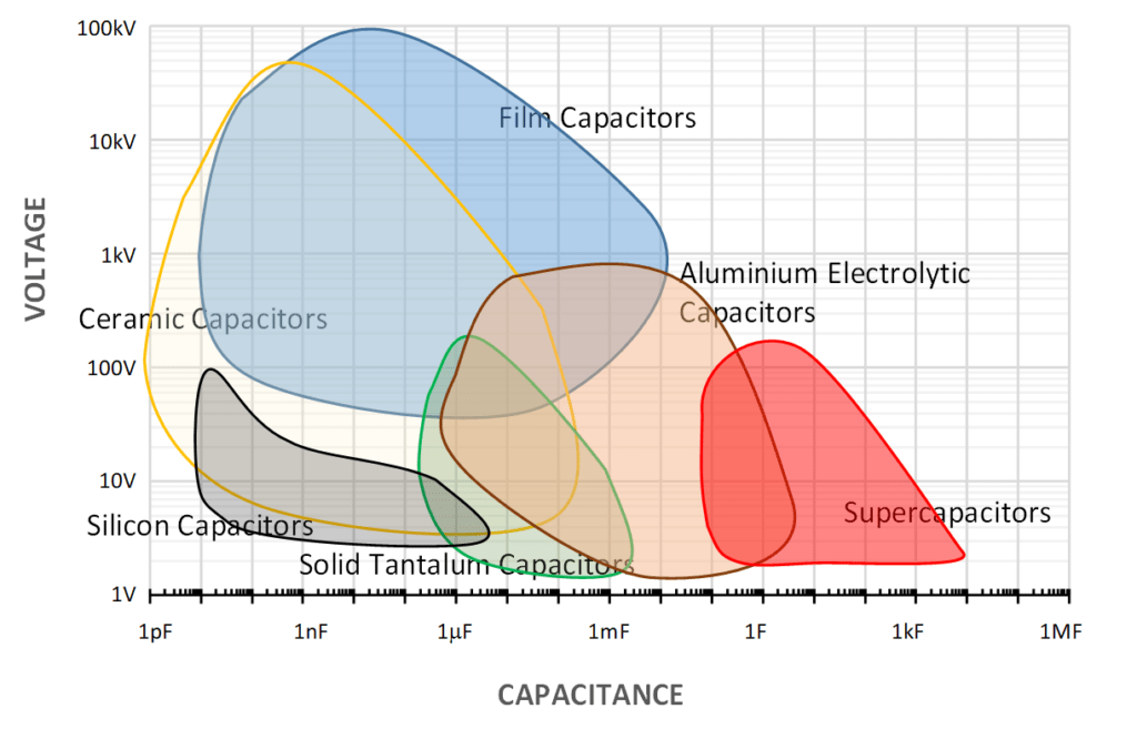
The amazing fact about capacitors today is that they cover over 17 ranges ! of its main parameter – CAPACITANCE this hardly achieved by any other components technology.

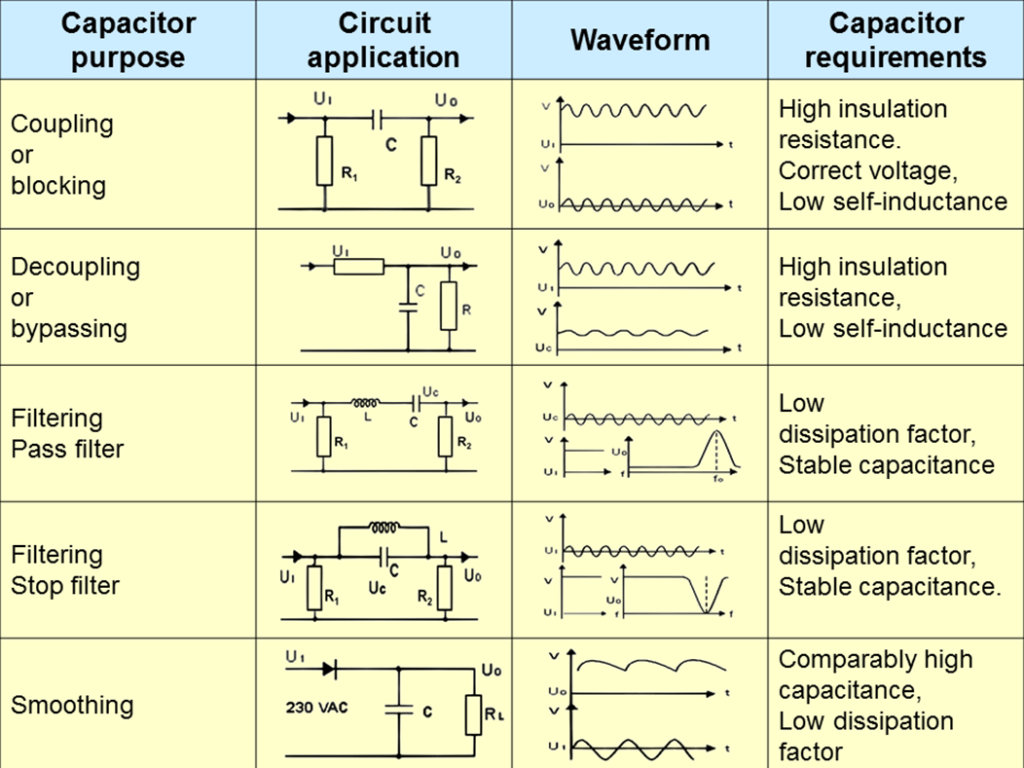
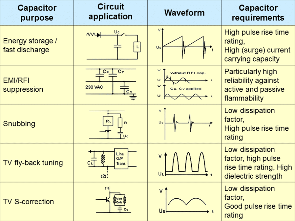
Applications – What is it good for ?

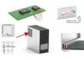
Capacitors are common elements in electrical circuits with number of applications and different requirements such as:

Fig.1. capacitor typical applications overview table

Here are further links with more insights about the capacitor circuit function and its selection guide:

  • Bypass Capacitors: Providing clean power to devices by filtering noise and suppressing transients on supply lines.
  • Decoupling Capacitors: Isolating sensitive components from noise by storing and releasing energy to maintain steady supply voltage during transients.
  • DC-Blocking Capacitors: Preventing unwanted DC offsets from corrupting the AC or RF signals in these systems.
  • DC Link Capacitors: acting as buffers that smooth power delivery and minimize ripples.
  • Safety Capacitors: Protecting circuits and mitigate energy hazards in high-voltage systems.  
  • EMI Filters: suppressing electromagnetic noise generated by switched-mode power supplies, motor drives, and other electronics.  
  • Snubber Capacitors: Absorbing voltage spikes, limiting over-voltages.
  • Resonant Capacitors: Leveraging this resonance to oscillate at specific frequencies, storing and releasing energy.
  • Flying Capacitors: Transferring charges between different voltage potentials in multi-level power inverters.
  • Bootstrap Capacitors: Enabling efficient high-side switching in half-bridge and full-bridge power converters.  
  • Power Back-Up and Load Management: Capacitors in battery-powered devices provide backup power in the event of disconnection or supply alternating current (AC) voltage for devices with heavy switching currents.
  • PFC Power Factor Correction Capacitors: Power factor correction circuits are used to minimize reactive power and enhance the efficiency with which inductive loads consume AC power.

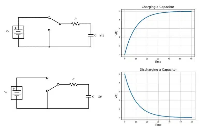
Basic Charge Storage and Discharge

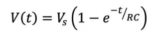
When connected to a direct current (DC) voltage source, capacitors charge almost instantaneously, but they can discharge just as fast if shorted; however, with some resistance in place, the rate of charge and discharge is exponential rather than direct (Figure 3).

The charging formula is expressed as:

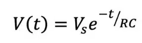
The discharging formula is expressed as:

Oscillators, waveform shapers and low-discharge power backup circuits are examples of electronics that leverage controlled charge and discharge rates.

Figure 3: Charging capacitor schematic and plotted behavior (top) compared to discharging capacitor schematic and plotted behavior (bottom).

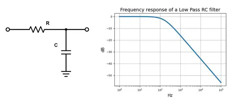
Bypassing and Low-Pass Filtering

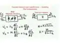
When placed in parallel with a signal path, capacitors take on a bypassing function. They allow DC to continue along the wire, but they divert high-frequency signal components to ground. In other words, capacitors play a role in low-pass filters, offering a low-impedance path for high-frequency signals to ground. In an RC low-pass filter (Figure 4), impedance decreases as frequency increases, so the ratio of VI to VO depends on the value of R, C and the signal frequency. When signals are low frequency and high impedance, energy goes to the output. When signals are high frequency and low impedance, energy is sent to ground.

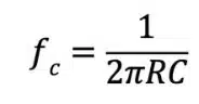
Frequency cutoff for an RC low-pass filter is expressed as:

Figure 4: An example of an RC low-pass filter (left) and its frequency response (right)

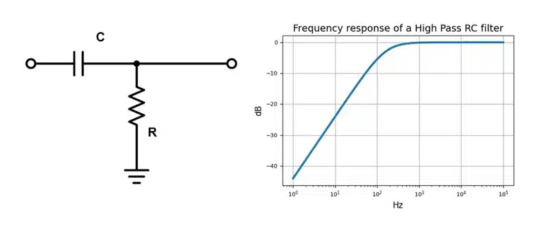
Coupling and High-Pass Filtering

When placed in series with the signal path, rather than in parallel, capacitors take on a different bypassing role. In this arrangement, they block DC while allowing AC signals to pass through the circuit. This function is called DC blocking or AC coupling.

The frequency cutoff for an RC high-pass filter is the same as for a RC low-pass filter:

In Figure 5, low-frequency signals see an impedance that is higher than R, so they go to ground. High-frequency signals see an impedance lower than R, resulting in a high-frequency output.

Figure 5: An example of an RC high-pass filter (left) and its frequency response (right).

Smoothing Circuit

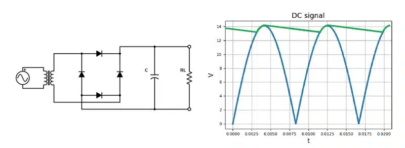
As mentioned, controlled capacitor charging and discharging serves multiple uses in electronics. For example, a full wave rectifier can use a capacitor to smooth rectified DC pulses and produce a more consistent DC output with less ripple (Figure 6).

The blue DC pulse is the result of a 60Hz AC signal at 10V root-mean-square (rms) passing through a rectifier. The smoothing capacitor charges at the top of each pulse and discharges until the next pulse rises, when it recharges the capacitor. The output across the load is noted in green on the plot.

Figure 6: Full wave rectifier with a ripple filter (left) and ripple output plot (right).

Timing and Waveform Shaping

A discussion of timing and waveform shaping is best with context. Here, we’ll use an RC relaxation oscillator (Figure 7). In these circuits, the voltage across the capacitor relaxes toward a time-varying target voltage.

Figure 7. An example of an RC relaxation oscillator (left) and its square wave output (right).

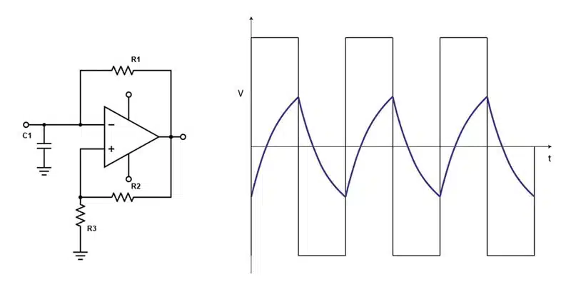
The capacitor is charged through a resistor and discharged when it reaches a certain threshold value, and this cycle repeats continuously. An amplifier, wired with positive feedback, controls the charging and discharging of the capacitor by acting like a switch triggered by the voltage threshold. The amplifier is also responsible for providing gain to the oscillator to maintain the oscillation. Figure 7 shows the switching behavior of the square wave output. Charging and discharging is represented by the blue waveform.

Further read:

Selection of Capacitors for DC/DC Converters

Related

Recent Posts

Modeling and Simulation of Leakage Inductance

9.5.2025
1

Murata and NIMS Built New Database of Dielectric Material Properties

5.5.2025
46

Shielding Cabinets

29.4.2025
17

Magnetic Shielding and Magnetic Shielding Sheets

29.4.2025
25

Corrosion its Development and Prevention

26.4.2025
25

Housing EMC Requirements, Issues and Solutions

26.4.2025
40

Hybrid Electrochemical Electrolytic Capacitor Provides High Frequency and High Capacitance Performance

25.4.2025
47

Non-Magnetic Interconnects

23.4.2025
13

RF Inductors Key Characteristics and Applications

17.4.2025
55

Electromagnetic Emissions Leakage in Enclosures

14.4.2025
40

Upcoming Events

May 14
11:00 - 12:00 CEST

Reliable RIGID.flex PCBs for Critical Applications – Made in Europe

May 14
17:00 - 17:30 CEST

Calculating Foil Winding Losses with AI

May 28
16:00 - 17:00 CEST

Power Over Data Line

View Calendar

Popular Posts

  • Buck Converter Design and Calculation

    0 shares
    Share 0 Tweet 0
  • Boost Converter Design and Calculation

    0 shares
    Share 0 Tweet 0
  • Flyback Converter Design and Calculation

    0 shares
    Share 0 Tweet 0
  • What is a Dielectric Constant and DF of Plastic Materials?

    4 shares
    Share 4 Tweet 0
  • LLC Resonant Converter Design and Calculation

    0 shares
    Share 0 Tweet 0
  • Ripple Current and its Effects on the Performance of Capacitors

    3 shares
    Share 3 Tweet 0
  • Dual Active Bridge (DAB) Topology Explained

    0 shares
    Share 0 Tweet 0
  • Tariffs Crush Sales Sentiment in April 2025 ECST Results

    0 shares
    Share 0 Tweet 0
  • Solid State Polymer Multilayer Capacitors For High Temperature Application

    0 shares
    Share 0 Tweet 0
  • SEPIC Converter Design and Calculation

    0 shares
    Share 0 Tweet 0

Newsletter Subscription


Passive Components Blog

© EPCI - Leading Passive Components Educational and Information Site

  • Home
  • Privacy Policy
  • EPCI Membership & Advertisement
  • About

No Result
View All Result
  • Home
  • Knowledge Blog
  • Premium Suppliers

© EPCI - Leading Passive Components Educational and Information Site

This website uses cookies. By continuing to use this website you are giving consent to cookies being used. Visit our Privacy and Cookie Policy.
Go to mobile version