Passive Components Blog
No Result
View All Result
  • Home
  • NewsFilter
    • All
    • Aerospace & Defence
    • Antenna
    • Applications
    • Automotive
    • Capacitors
    • Circuit Protection Devices
    • electro-mechanical news
    • Filters
    • Fuses
    • Inductors
    • Industrial
    • Integrated Passives
    • inter-connect news
    • Market & Supply Chain
    • Market Insights
    • Medical
    • Modelling and Simulation
    • New Materials & Supply
    • New Technologies
    • Non-linear Passives
    • Oscillators
    • Passive Sensors News
    • Resistors
    • RF & Microwave
    • Telecommunication
    • Weekly Digest

    YAGEO Extends Antenna Portfolio with Wi‑Fi 6E/7 and Tri‑band GNSS Solutions

    SCHURTER Introduces 2410 SMD Fuse for Robust AC/DC Protection

    TDK Releases High Temp 175C Automotive NTC thermistors

    TU Wien Sets New Benchmark in Superconducting Vacuum Gap nanoCapacitors

    2026 Power Magnetics Design Trends: Flyback, DAB and Planar

    Vishay Releases Sulfur‑Resistant Chip Resistors

    Würth Elektronik Introduces Lead-Free SMT Spacers

    Schurter Releases EKO HV Fuses up to 1000 VDC, 1100 A

    Empower Releases High-Density Embedded Silicon Capacitors

    Trending Tags

    • Ripple Current
    • RF
    • Leakage Current
    • Tantalum vs Ceramic
    • Snubber
    • Low ESR
    • Feedthrough
    • Derating
    • Dielectric Constant
    • New Products
    • Market Reports
  • VideoFilter
    • All
    • Antenna videos
    • Capacitor videos
    • Circuit Protection Video
    • Filter videos
    • Fuse videos
    • Inductor videos
    • Inter-Connect Video
    • Non-linear passives videos
    • Oscillator videos
    • Passive sensors videos
    • Resistor videos

    2026 Power Magnetics Design Trends: Flyback, DAB and Planar

    Enabling Software‑Defined Vehicle Architectures: Automotive Ethernet and Zonal Smart Power

    Calculating Resistance Value of a Flyback RC Snubber 

    One‑Pulse Characterization of Nonlinear Power Inductors

    Thermistor Linearization Challenges

    Coaxial Connectors and How to Connect with PCB

    PCB Manufacturing, Test Methods, Quality and Reliability

    Transformer Behavior – Current Transfer and Hidden Feedback

    Choosing the Right Capacitor: The Importance of Accurate Measurements

    Trending Tags

    • Capacitors explained
    • Inductors explained
    • Resistors explained
    • Filters explained
    • Application Video Guidelines
    • EMC
    • New Products
    • Ripple Current
    • Simulation
    • Tantalum vs Ceramic
  • Knowledge Blog
  • DossiersNew
  • Suppliers
    • Who is Who
  • PCNS
    • PCNS 2025
    • PCNS 2023
    • PCNS 2021
    • PCNS 2019
    • PCNS 2017
  • Events
No Result
View All Result
Passive Components Blog
No Result
View All Result

Bourns Releases High‑Q Air Coil Inductors for RF Aplications

29.1.2026
Reading Time: 6 mins read
A A

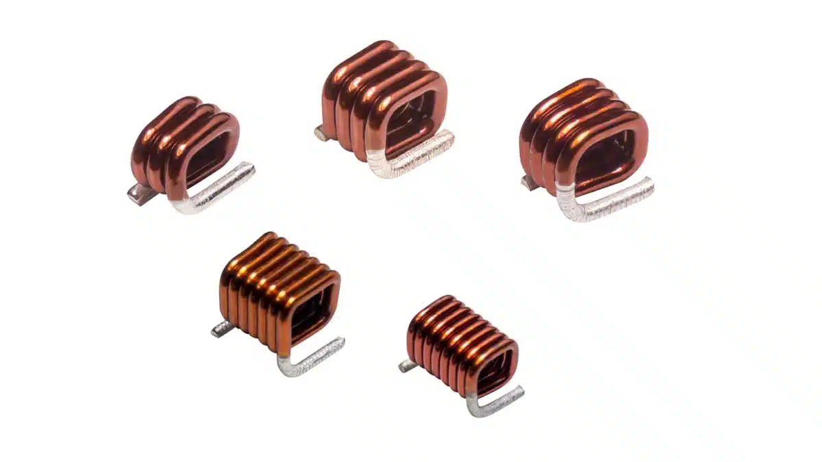
Bourns has introduced a new family of high‑Q air coil inductors covering multiple package footprints and inductance ranges for RF front‑end, tuning and amplifier stages.

The AC3028SQ, AC5037SQ, ACXX14SQ, ACXX15SQ and ACXX18SQ air coil inductor series target designers who need tight tolerance, low DCR and mechanically robust SMT inductors in high‑frequency TV, radio and RF equipment.

RelatedPosts

Bourns SSD‑1000A AEC‑Q Digital Current Sensors

Bourns BTJ Thermal Jumper Chips for PCB Heat Management

Bourns Releases 500VDC 690VAC Fuse to Protect Power Semiconductors

Key features and benefits

The new air coil inductors combine high Q, low series resistance and controlled inductance in compact SMT formats.

  • Inductance range from 5.5 nH up to 82 nH, covering typical RF matching, tank and filter values in VHF/UHF front ends and low‑power RF amplifiers.
  • High Q factor up to 230, helping minimize insertion loss and improve selectivity in band‑pass filters, oscillators and tuned circuits.
  • Tight inductance tolerances of 2% and 5%, reducing spread in gain, center frequency and impedance matching and simplifying production trim.
  • Very low DCR from 3.4 mΩ to 12 mΩ max (depending on series), which helps maintain efficiency and reduce thermal rise at RF and intermediate frequency currents.
  • Rated current capability from 2.7 A to 5.6 A, allowing use in higher‑power RF stages and driver amplifiers without saturating or causing excessive temperature rise.
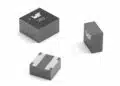
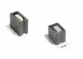
  • Flat top and bottom terminations for good mechanical stability, reliable solder joint formation and compatibility with standard pick‑and‑place processes.
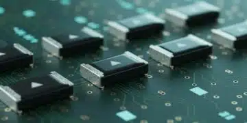
  • Surface‑mount construction optimized for reflow, supporting automated assembly on standard FR‑4 RF boards and mixed‑technology PCBs.
  • Operating temperature range from −25 °C to +125 °C, suitable for many industrial, broadcast and telecom environments.
  • RoHS compliant construction according to the current directive and annex, facilitating use in global production without additional material exemptions.

In practice, the combination of high Q and tight tolerance makes these parts especially attractive where filter skirts, oscillator phase noise or narrowband selectivity are critical and every fraction of a dB counts.

Typical applications

The series is aimed at classic RF and tuning functions rather than power magnetics.

  • High‑frequency TV and radio receivers, including RF front‑ends, tracking filters and IF stages.
  • Radio transmitters in broadcast, land‑mobile and ISM bands that require stable matching networks and low‑loss output filters.
  • RF amplifiers from low‑noise front‑end stages up to driver levels within the rated current envelope.
  • Tuning applications such as LC resonators, VCO tanks and narrowband band‑pass filters where air core behavior and high Q are important.

Beyond the explicitly listed use cases, these series are also relevant in test and measurement RF fixtures, small signal filters in instrumentation, and where designers prefer air core inductors to avoid core material non‑linearity.

Technical highlights

SeriesSize (L × W × H, mm)Inductance range (nH)Q value (typ.)Rated current (A)Operating temperature (°C)Notes
AC3028SQ2.67–3.30 × 2.67 × 2.7927 – 472004.4 – 5.5−25 to +125Medium SMT, high‑Q, higher current
AC5037SQ4.06–5.84 × 3.56 × 3.7347 – 822304.9 – 5.6−25 to +125Largest size, highest Q, higher L
ACXX14SQ1.30–2.59 × 1.83 × 1.405.5 – 19.460 – 902.9−25 to +125Very small, low–mid L, compact tuning
ACXX15SQ1.30–2.59 × 1.83 × 1.526.9 – 2290 – 1002.7−25 to +125Small, slightly higher L and Q
ACXX18SQ1.47–2.97 × 2.13 × 1.838.1 – 3390 – 1304.4−25 to +125Mid‑size, higher current, mid L range

Design‑in notes for engineers

When designing with air coil inductors, Q, tolerance and parasitics are usually more critical than absolute inductance.

  • Use high‑Q series (for example AC5037SQ and AC3028SQ) in places where filter insertion loss, group delay or phase noise is sensitive, such as IF filters, VCO tanks or output matching networks.
  • In compact RF modules, consider ACXX14SQ or ACXX15SQ for impedance matching and tuning, but account for their somewhat lower Q at the smallest footprints when estimating total filter loss.
  • Ensure that the rated current of the selected part exceeds the expected RF current, including modulation peaks and mismatch conditions; note that low DCR helps reduce self‑heating, but total temperature rise is still governed by ambient conditions and board layout.
  • Board layout is critical at VHF/UHF: keep pads and connections short, maintain a controlled RF ground and consider the influence of nearby copper and components on inductance and Q.
  • Because these parts are air core, they avoid saturation and core loss effects but are more susceptible to coupling and external magnetic fields; maintain adequate spacing and orientation to minimize unwanted mutual coupling in dense RF sections.
  • The flat top and bottom geometry is beneficial for automated optical inspection and coplanarity, but you should still follow standard reflow profiles and land pattern recommendations from the datasheets.

For new designs or drop‑in replacements, always compare the self‑resonant frequency and Q at the operating frequency against existing components to ensure equivalent or better performance.

Source

This article is based on information provided in an official new product release from Bourns for the AC3028SQ, AC5037SQ, ACXX14SQ, ACXX15SQ and ACXX18SQ air coil inductor series, with additional independent editorial context and design considerations.

References

  1. Bourns new product release – Air Coil Inductors AC3028SQ, AC5037SQ, ACXX14SQ, ACXX15SQ, ACXX18SQ (PDF)

Related

Recent Posts

2026 Power Magnetics Design Trends: Flyback, DAB and Planar

13.2.2026
25

Vishay Releases Compact 0806 Low‑DCR Power Inductor

5.2.2026
33

Murata Publishes Power Delivery Guide for AI Servers

4.2.2026
119

Selecting Current Sense Transformers with Würth Elektronik REDEXPERT

3.2.2026
32

Enabling Software‑Defined Vehicle Architectures: Automotive Ethernet and Zonal Smart Power

2.2.2026
38

CMSE 2026 Announces Call for Presentations on High-Reliability Military and Space Electronics

28.1.2026
53

ESA Call for Papers 6th Space Passive Component Days – SPCD 2026

28.1.2026
56

Modelithics Releases Component Model Library for SIMULIA CST Studio Suite

27.1.2026
39

Würth Elektronik Developed a Custom Transformer for Active Hand Orthosis

26.1.2026
50

Upcoming Events

Feb 24
16:00 - 17:00 CET

Mastering Galvanic Isolation: Ensuring Safety in Power Electronics

Mar 3
16:00 - 17:00 CET

Cybersecurity at the Eleventh Hour – from RED to CRA – Information and Discussion

Mar 21
All day

PSMA Capacitor Workshop 2026

View Calendar

Popular Posts

  • Buck Converter Design and Calculation

    0 shares
    Share 0 Tweet 0
  • Boost Converter Design and Calculation

    0 shares
    Share 0 Tweet 0
  • LLC Resonant Converter Design and Calculation

    0 shares
    Share 0 Tweet 0
  • Flyback Converter Design and Calculation

    0 shares
    Share 0 Tweet 0
  • Ripple Current and its Effects on the Performance of Capacitors

    3 shares
    Share 3 Tweet 0
  • Dual Active Bridge (DAB) Topology

    0 shares
    Share 0 Tweet 0
  • What is a Dielectric Constant and DF of Plastic Materials?

    4 shares
    Share 4 Tweet 0
  • MLCC and Ceramic Capacitors

    0 shares
    Share 0 Tweet 0
  • 3-Phase EMI Filter Design, Simulation, Calculation and Test

    0 shares
    Share 0 Tweet 0
  • MLCC Case Sizes Standards Explained

    0 shares
    Share 0 Tweet 0

Newsletter Subscription


Passive Components Blog

© EPCI - Leading Passive Components Educational and Information Site

  • Home
  • Privacy Policy
  • EPCI Membership & Advertisement
  • About

No Result
View All Result
  • Home
  • Knowledge Blog
  • PCNS

© EPCI - Leading Passive Components Educational and Information Site

This website uses cookies. By continuing to use this website you are giving consent to cookies being used. Visit our Privacy and Cookie Policy.
Go to mobile version