This video from Würth Elektronik elaborates on clearance and creepage distance and solid insulation materials.
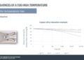
Many applications of fire are productive and warming. Fire can be a real risk if the components on pcb has not been selected correctly for high voltages.
In some circumstances, incorrectly selected components can create Transient voltage, which could cause damage to the board and even leads to spark fire. To achieve electric shock protection, electronic equipment must have an effective insulation method, which can be divided in to clearance and creepage distance and solid insulation materials.
Creepage and Clearance
Creepage and clearance are crucial product safety terms and requirements for various products, assemblies, and components. Regulatory agencies like IEC, UL, and CSA establish specific product application guidelines and requirements that must be met to sell products in many countries.
Creepage and clearance standards ensure safe operation, reducing the risk of electric shocks or other injuries to end users and minimizing fire hazards. Additionally, these standards protect other components in close proximity to those being rated or tested to prevent a failure from spreading throughout the system. This discussion will focus on power interconnects, printed wiring boards (PWB/PCB), and cable assemblies.
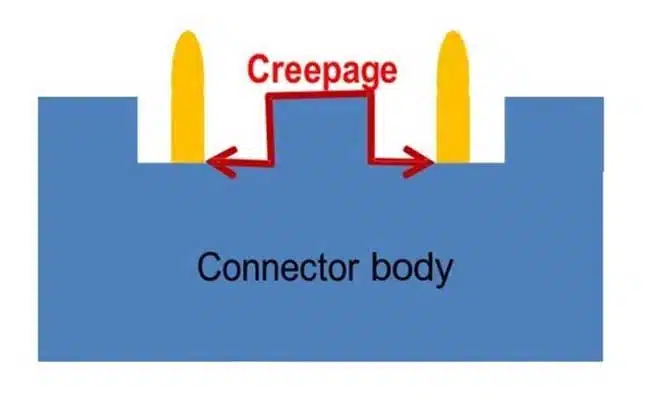
What is Creepage?
Creepage refers to the linear distance along all insulating surfaces between two electrical conductors (as seen in Figure below). In terms of electrical measurements, this parameter essentially equates to a surface insulation resistance measurement (SIR or IR). It’s important to note that since creepage encompasses the entire surface distance between the conductors, it significantly exceeds the clearance distance of the same contacts.
What is Clearance?
Clearance refers to the distance between two electrical conductors in the air. In simpler terms, it represents the distance a spark needs to travel to cause a dielectric breakdown, as illustrated in Figure below.