


Designing an LLC transformer where the resonant inductance is fully integrated into the transformer leakage is a powerful way to shrink magnetics and improve efficiency in high‑density power supplies.
This approach, however, exposes all the practical limits of core sizing, leakage control, copper losses and thermal margins that are often hidden by first‑order equations.
The following article written by Dr. Molina, Frenetic walks through a realistic 2 kW, 800 V to 48 V LLC converter design using an integrated resonant inductor, highlighting how to select and , estimate core size and leakage, and then close the loop with simulation‑driven iteration.
Key Takeaways
- The article outlines the process of designing an LLC transformer with integrated resonant inductance for high-density power supplies.
- It highlights practical challenges such as core sizing, leakage control, and the need for simulation-driven iteration.
- Key design parameters include a 2 kW output, 800 V input, and 48 V output, targeting an efficiency above 97%.
- The article emphasizes the importance of the L_m/L_r ratio in shaping gain curves and the role of effective quality factor Q_e.
- Final design choices involve selecting suitable cores and managing thermal performance while maintaining good control characteristics.
Design target and operating context
For this example, the LLC stage targets a telecom/industrial‑class DC‑DC converter around the 2 kW level with a high‑voltage front end.
- Topology: LLC resonant converter
- Input: 800 V DC bus (fixed for this study)
- Output: 48 V DC
- Output power: approximately 2 kW
- Nominal resonant frequency: about 100 kHz
- Efficiency target: above 97%
The key requirement is to integrate the resonant inductance into the transformer leakage inductance, eliminating a separate resonant choke. This places tight constraints on the core geometry, winding scheme and allowable temperature rise, because the “transformer” now carries both isolation and resonant energy‑storage functions.
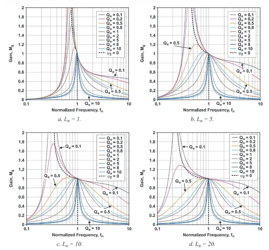
LLC Gain Model
Using the Fundamental Harmonic Analysis (FHA) approach (as described in TI’s SLUP263), the LLC voltage gain can be approximated as:
where:
- Mg: Magnitude of the LLC converter voltage gain (output‑to‑input ratio in fundamental harmonic analysis).
- : Normalized inductance ratio, defined as , where is the magnetizing inductance and is the resonant inductance.
- : Normalized switching frequency, defined as , where is the actual switching frequency and is the resonant frequency of the tank.
- : Effective quality factor of the resonant tank, which depends on the load resistance reflected to the primary and the values of Lr and the resonant capacitance.
Why the ratio matters
Different values reshape the gain curve:
- Lower : sharper gain peak, higher gain sensitivity, narrower usable frequency range.
- Higher : flatter gain curve, broader frequency span, typically easier control at the cost of different current waveforms.
The role of and resonant capacitance
The effective quality factor is shaped by:
- Resonant inductance and resonant capacitance
- Reflected load resistance to the primary
For a given power level and bus voltage, links the tank design to the expected load range. The resonant capacitor selection is non‑trivial: the chosen capacitance must support control requirements, soft‑switching windows and component availability. In this design walkthrough, is treated as a degree of freedom to be fixed later once the magnetic structure is stable; the focus is on the transformer plus integrated .
Choosing Initial Design Values
We’re going to use the Frenetic Magnetic Simulator to find a design. Even though we understand the theory, the Frenetic Simulator still requires you to input numerical values for Lm and Lr.
In practice, a moderate value such as is often chosen early as a good compromise between gain sensitivity and control range. The study further assumes an effective quality factor as an initial, well‑behaved operating point.
These values tend to produce stable and well-behaved gain curves, making them a good initial point for design exploration.
Now we need to put pen to paper and get some actual values for Lm and Lr.
Estimating core size using area product
Before assigning absolute values to and , it is essential to estimate how large the transformer should be. The achievable leakage inductance is tightly linked to core geometry and winding layout, so starting from a realistic core size avoids chasing impossible combinations of inductance and loss.
A practical way to estimate core size is the area‑product method. The area product combines core cross‑section area and winding window area into a single figure of merit related to apparent power:Where:
- Aw = winding window area (cm2).
- Ac = core cross-section area (cm2).
A more practical expression relates the area product to the transformer power capability directly:
Where:
- Pt apparent power (w).
- Kf waveform factor (4.44 for sinusoidal excitation, 4 for square wave excitation).
- Ku = window utilization factor (usually between 0.2-0.4).
- Bm = peak flux density (T).
- J = current density (A/cm2).
- f switching frequency (Hz).
Remember, the apparent power includes both primary and secondary power throughput:
CASE STUDY
Assumed Design Parameters
For this design I’ll choose conservative but realistic values:
- Output power : 2000 W
- Efficiency : 0.97 (implying about 60 W total loss budget)
- Waveform factor : 4 for square‑wave type excitation
- Window utilization : approximately 0.25
- Peak flux density : around 0.12 T (conservative for 100 kHz ferrite)
- Current density : about 4 A/mm²
- Switching frequency : 100 kHz
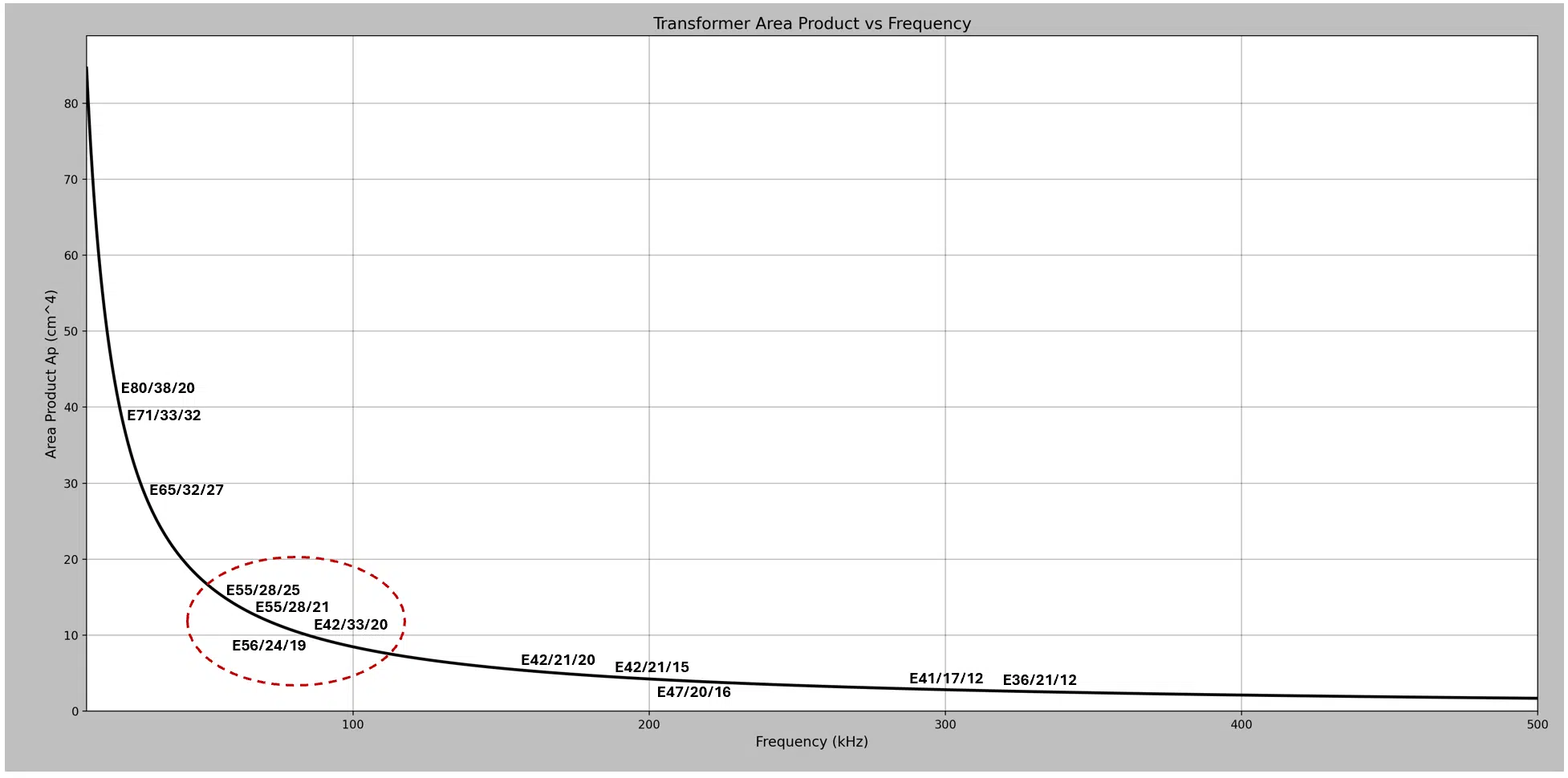
With these assumptions, the estimated area product is on the order of 8 cm4. This points toward medium‑to‑large E‑cores as suitable candidates, such as:
- E55
- E56
- E42
This initial sizing is intentionally approximate and serves to narrow down core families rather than pick a final part number.
Once a core candidate is selected, we can estimate the minimum number of primary turns required to keep the flux density below our target.
Estimating the minimum primary turns
For each potential core, the minimum primary turns are chosen so that the peak flux density remains below the target at 800 V input and the intended operating frequency.
This yields a first‑order turn count which:
- Limits core loss by constraining peak flux.
- Determines copper cross‑section needs from current density.
- Sets the scale for both magnetizing and leakage inductances.
Even if a simulator will later refine the exact turns, having a minimum turns estimate is necessary to predict the feasible leakage inductance range.
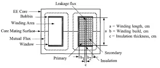
Estimating leakage inductance as resonant
Because the resonant inductance is fully integrated into the transformer, the leakage inductance of the winding geometry becomes the design’s . Classical rules of thumb such as McLyman’s formulas approximate leakage for layered windings, using physical dimensions like:
- Winding width and height
- Spacing between primary and secondary
- Interleaving pattern
These formulas are sensitive to assumptions about insulation thickness and layout. For a design where leakage inductance is a key functional parameter rather than a parasitic, this sensitivity must be treated with caution. Nevertheless, the approximations give a useful starting point for:
- Selecting an initial layer stack‑up.
- Assessing whether the target is even feasible for a given core size.
With an estimated leakage for the chosen core and turns, can be set using the target inductance ratio. For example, if leakage is around 10 µH and , then:
These values then feed into a magnetic simulation tool for detailed optimization.
Simulation‑driven design with Frenetic
The study uses the Frenetic Magnetic Simulator to explore many transformer variants quickly. Starting from the analytical estimates, the tool evaluates:
- Magnetizing inductance and leakage
- Core and copper losses
- Temperature rise and hot‑spot behavior
- Achieved inductance ratio
Across 33 different designs and multiple core sizes, the simulations reveal several important realities for integrated LLC magnetics.
Observation 1 – initial area product was optimistic
Smaller cores derived from the 8 cm estimate struggled to meet both loss and temperature limits at 2 kW. With the integrated resonant function, the transformer carries substantial reactive energy and copper stress, so the actual required core volume is larger than a simple area‑product estimate suggests. In practice:
- Undersized cores lead to excessive temperature rise.
- Pushing flux or current density hard to save volume quickly erodes the loss budget.
Observation 2 – analytical leakage estimates are optimistic
The leakage inductance predicted by simple formulas often deviated from the simulation results. In an LLC design where leakage is intentionally raised and controlled:
- Small changes in spacing or layer order significantly alter leakage.
- Realistic insulation and manufacturability constraints limit how aggressively one can “tune” leakage via geometry.
This underscores that leakage needs to be validated by field‑solving or high‑fidelity simulation, not just pencil‑and‑paper rules.
Observation 3 – lower increases thermal stress
The design exercise shows a clear trend: as decreases, thermal performance worsens, even when core size and basic flux limits are similar. The reason is primarily copper‑related:
- Lower means higher magnetizing current to establish the same flux swing.
- Larger or distributed air gaps increase fringing fields and local AC losses.
- The combination raises AC copper loss, pushing winding temperatures upward.
For an integrated resonant design, this effectively limits how low can be pushed without compromising thermal headroom.
Observation 4 – larger cores ease thermals but push upward
Scaling to larger cores generally reduces flux density and current density for a given power level, improving thermal margins and lowering losses. However:
- Fewer turns are needed on larger cores.
- With shorter mean length per turn and more compact windings, leakage inductance tends to decrease.
- With shrinking while remains relatively high, the achieved drifts above the original target.
The net effect is that bigger cores make it easier to meet thermal targets but harder to hold near 5. Designers often face a trade‑off: accept a higher and adapt control strategy, or accept tighter thermal margins.
Observation 5 – leakage is relatively stable per core family
For a given core geometry, the achievable leakage inductance did not vary as dramatically as one might expect:
- Current density constraints limit how much the turn count can be altered.
- Basic winding geometry (number of layers, relative positions of primary and secondary) remains similar across variants.
- Only moderate tweaks to winding width and spacing are practical.
This suggests that, for a chosen core family, there is only a narrow band of feasible leakage values without radical changes to the winding concept.
Final design choice and key numbers
After exploring the design space, the selected solution uses:
- Core: E65/32/27 ferrite core
- Primary turns: 34 turns
- Total losses: about 14.66 W in the transformer
- Maximum temperature: around 88 °C under the specified operating conditions
- Inductance ratio:
This design comfortably fits within a 2 kW/97% efficiency target with a shared loss budget of about 60 W and a transformer allocation of roughly 24 W. The achieved 14.66 W of losses leaves margin for control, EMI, and mechanical uncertainties while maintaining a reasonable temperature rise.
Although the final is higher than the initial target of 5, the design is considered practical and controllable. It provides:
- Solid thermal performance on a realistic core size.
- Integrated resonant inductance sufficient to avoid an external inductor.
- A robust starting point for further converter‑level optimization.
The resonant capacitor and precise switching frequency plan remain important tuning knobs at the converter level. Adjusting these can compensate for the higher during control loop design and fine‑tune the gain curve without reopening the magnetic stack from scratch.
Typical applications for this LLC transformer approach
An LLC transformer with integrated resonant inductance and a 2 kW, 800 V to 48 V profile is well aligned with a range of high‑density power conversion tasks:
- Telecom and datacenter DC‑DC modules on high‑voltage intermediate buses.
- Industrial DC supplies from rectified 3‑phase or PFC‑boosted mains around 800 V.
- EV on‑board chargers or DC fast‑charging second‑stage converters with 48 V rails.
- High‑power server or storage power units requiring compact magnetics and high efficiency.
The integration of the resonant inductor directly into the transformer is particularly attractive anywhere PCB real estate and component height are constrained, or where layout simplicity and reduced parasitics are key to EMI performance.
Design‑in notes for magnetics engineers
When designing or specifying an LLC transformer with integrated resonant inductance, the following practical points are useful:
- Treat as a range, not a fixed target. Aim for a band (for example, 5–8) that meets gain and control requirements while still leaving thermal and mechanical margin.
- Use area‑product calculations as a lower bound. For high‑density resonant designs, assume you will need a somewhat larger core than first‑order theory suggests.
- Consider early constraints on current density and temperature rise. Working backward from allowable hot‑spot temperatures often pushes designs toward larger cores and more parallel copper.
- Reserve design freedom in the resonant capacitor and frequency plan. Because may shift after realistic thermal and leakage constraints are applied, allow and the frequency range to adapt later.
- Simulate leakage and AC losses with realistic geometry. Approximate formulas are useful to get started but can be misleading when the leakage inductance is intentionally high and functionally critical.
- Keep manufacturability in mind. Complex winding schemes that “look good” in simulation may be challenging or expensive to build; iterative simulation should include practical layer counts, insulation systems and terminations.
For purchasing engineers, it is important to recognize that such a transformer is not a commodity catalog part. It is usually an application‑specific magnetic component, designed around:
- A particular core family (for example, E65/32/27 ferrite of a defined material).
- Specific turns, wire types (round or foil) and insulation systems.
- Verified loss and temperature profiles at the intended operating point.
Sourcing strategies should therefore focus on manufacturers experienced in custom high‑frequency magnetics and on establishing clear specifications for , , inductance tolerance over temperature, isolation ratings and test conditions.
Source
This article summarizes and interprets a detailed 2 kW LLC transformer design example with integrated resonant inductance, based on a technical design walkthrough published by the original author. Numerical values, core choice and qualitative trends follow the example content, while additional commentary focuses on design‑in implications for engineers and buyers.
FAQ – Designing a 2 kW LLC Transformer with Integrated Resonant Inductor
The goal is to design a 2 kW, 800 V to 48 V LLC transformer where the resonant inductance is fully integrated into the transformer leakage, eliminating a separate resonant inductor and achieving high efficiency around 97%.
The inductance ratio strongly shapes the gain curve of the LLC converter, affecting gain sensitivity, the required frequency range for regulation, and overall control behavior, so it must be chosen as a design trade‑off rather than a purely theoretical value.
The effective quality factor , determined by , and the reflected load resistance, affects the sharpness of the gain peak and the shape of the resonant response, linking the magnetic design to the load and control dynamics.
The initial core size is estimated using the area product method, which relates core cross‑section, window area, flux density, frequency and current density to the apparent power, giving a first guess of suitable E‑core families for a 2 kW design.
First‑order methods give rough values for area product, turns and leakage, but leakage inductance and AC losses depend strongly on real geometry; simulation tools such as Frenetic are needed to accurately predict , , losses and temperature before building hardware.
The design aimed for , transformer losses below about 24 W within a 60 W total loss budget, and a temperature rise limited to roughly 100 °C to keep the design practical for cooling and long‑term reliability.
Simulations showed that the area‑product estimate was optimistic, smaller cores ran too hot, analytical leakage estimates were often too high, and for a given core family the achievable leakage range was narrower than simple formulas suggested.
Lower requires lower magnetizing inductance, which increases magnetizing current and often requires larger or distributed air gaps, leading to higher AC copper losses and fringing‑field heating that push winding temperature upward.
Larger cores reduce flux and current density and improve thermal behavior, but they also reduce leakage inductance for a given turns arrangement, which tends to increase and move the design away from the original target gain characteristics.
The final practical solution used an E65/32/27 ferrite core with 34 primary turns, total transformer losses of about 14.66 W and a maximum temperature near 88 °C, resulting in an inductance ratio of approximately 7.7 instead of the initial target of 5.
Although increases control sensitivity compared with 5, the configuration meets power, efficiency and thermal requirements, provides integrated resonant inductance without a separate inductor, and offers a robust starting point for converter‑level optimization.
The study shows that relying solely on area‑product and textbook leakage formulas is insufficient for integrated‑resonant LLC transformers; accurate simulation and iterative exploration of geometry are essential to find realistic trade‑offs between , losses, temperature and manufacturability.
How‑to – Design a 2 kW LLC Transformer with Integrated Resonant Inductor
- Step 1 – Define electrical targets
Specify the main converter parameters such as: LLC topology, 800 V DC input bus, 48 V output, 2 kW power level, nominal switching frequency around 100 kHz and an efficiency target above 97%, and decide that the resonant inductance will be fully integrated into the transformer leakage.
- Step 2 – Choose initial Ln and Qe
Use the Fundamental Harmonic Analysis model to select an initial inductance ratio (for example around 5) and an effective quality factor (for example around 0.5) that give a well‑behaved gain curve and reasonable frequency range for regulation.
- Step 3 – Estimate area product and candidate cores
Apply the area‑product method with realistic assumptions for waveform factor, window utilization, peak flux density, current density, frequency and apparent power to estimate the required area product (roughly 8 cm in this case) and shortlist suitable E‑core families such as E55, E56 or E42.
- Step 4 – Calculate minimum primary turns
For each candidate core, estimate the minimum primary turns using the flux‑density limit at 800 V and 100 kHz so that the peak flux stays within the chosen , which also sets the approximate current density, copper cross‑section and starting point for magnetizing inductance.
- Step 5 – Approximate leakage inductance as Lr
Using the assumed core, turns and window geometry, approximate the leakage inductance with a rule such as McLyman’s formula, interpreting it as the resonant inductance and recognizing that insulation thickness, spacing and layer structure heavily influence the final value.
- Step 6 – Derive magnetizing inductance Lm
From the target inductance ratio and the estimated leakage compute the required magnetizing inductance to obtain a consistent set of tank parameters that can be fed into a magnetic simulator.
- Step 7 – Run magnetic simulations and iterate
Load the candidate cores, turns, and into a tool such as Frenetic, then iterate across winding arrangements, gaps and wire options while monitoring achieved inductances, core and copper losses and hot‑spot temperature for each configuration.
- Step 8 – Analyze trends and adjust targets
Use the simulation results to observe how changing core size and winding layout affects , leakage, losses and temperature, and be prepared to relax the original target or upsizing the core when smaller cores overheat or when realistic leakage values do not match analytical estimates.
- Step 9 – Select a practical transformer solution
Choose the configuration that best balances thermal limits, efficiency and controllability; in this study an E65/32/27 core with 34 turns, about 14.66 W loss, 88 °C maximum temperature and was selected as a robust, manufacturable design.
- Step 10 – Reserve degrees of freedom at converter level
With the transformer fixed, plan to fine‑tune resonant capacitance, frequency range and control strategy around the realized and , using system‑level simulation and hardware validation to refine the gain curve and ensure reliable operation under real‑world load and input variations.