Passive Components Blog
No Result
View All Result
  • Home
  • NewsFilter
    • All
    • Aerospace & Defence
    • Antenna
    • Applications
    • Automotive
    • Capacitors
    • Circuit Protection Devices
    • electro-mechanical news
    • Filters
    • Fuses
    • Inductors
    • Industrial
    • Integrated Passives
    • inter-connect news
    • Market & Supply Chain
    • Market Insights
    • Medical
    • Modelling and Simulation
    • New Materials & Supply
    • New Technologies
    • Non-linear Passives
    • Oscillators
    • Passive Sensors News
    • Resistors
    • RF & Microwave
    • Telecommunication
    • Weekly Digest

    Bourns Releases High Current Metal Alloy-based, Multilayer Power Chip Inductors

    Smiths Interconnect Extends Space-Qualified, High-Reliability Fixed Chip Attenuators 

    Samtec Expands Offering of Slim, High-Density HD Array Connectors

    Bourns Unveils High-Precision Wirewound Resistor with Long-Term Stability

    Common Mode Chokes Selection for RF Circuits in Next-Generation Communication Systems

    Capacitor Self-balancing in a Flying-Capacitor Buck Converter

    Littelfuse Acquires Basler Electric Enhancing High-Growth Industrial Market

    DigiKey Grows Inventory with Over 31K New Stocking Parts in Q3 2025

    Murata Expands Automotive Metal Frame Y2/X1 Safety MLCC Capacitors to 500V

    Trending Tags

    • Ripple Current
    • RF
    • Leakage Current
    • Tantalum vs Ceramic
    • Snubber
    • Low ESR
    • Feedthrough
    • Derating
    • Dielectric Constant
    • New Products
    • Market Reports
  • VideoFilter
    • All
    • Antenna videos
    • Capacitor videos
    • Circuit Protection Video
    • Filter videos
    • Fuse videos
    • Inductor videos
    • Inter-Connect Video
    • Non-linear passives videos
    • Oscillator videos
    • Passive sensors videos
    • Resistor videos

    Common Mode Chokes Selection for RF Circuits in Next-Generation Communication Systems

    Capacitor Self-balancing in a Flying-Capacitor Buck Converter

    How to Select Ferrite Bead for Filtering in Buck Boost Converter

    Power Inductors Future: Minimal Losses and Compact Designs

    Percolation Phenomenon: Degradation of Molded Power Inductors in DC/DC Converters

    Connector PCB Design Challenges

    Efficient Power Converters: Duty Cycle vs Conduction Losses

    Ripple Steering in Coupled Inductors: SEPIC Case

    SEPIC Converter with Coupled and Uncoupled Inductors

    Trending Tags

    • Capacitors explained
    • Inductors explained
    • Resistors explained
    • Filters explained
    • Application Video Guidelines
    • EMC
    • New Products
    • Ripple Current
    • Simulation
    • Tantalum vs Ceramic
  • Knowledge Blog
  • Suppliers
    • Who is Who
  • PCNS
    • PCNS 2025
    • PCNS 2023
    • PCNS 2021
    • PCNS 2019
    • PCNS 2017
  • Events
No Result
View All Result
Passive Components Blog
No Result
View All Result

Effect of Resistor TCR Tracking to Analog and A/D Signal Processing

4.12.2019
Reading Time: 7 mins read
A A

Ove Hach in his EDN article explains effect of resistor TCR tracking and its precision requirements with respect to analogue and A/D signal processing tasks.

The progress in digitization has profoundly changed our lives. There is no area of everyday life to which digital circuits haven’t penetrated. Ever more powerful microcontrollers and data converters make let you convert analog signals into high resolution digital signals. What do you need to consider in selecting the resistors for the upstream measurement amplifier? What possible errors can you avoid so that the analog circuit fits with the digital circuit?

RelatedPosts

Bourns Releases High Current Metal Alloy-based, Multilayer Power Chip Inductors

Smiths Interconnect Extends Space-Qualified, High-Reliability Fixed Chip Attenuators 

Samtec Expands Offering of Slim, High-Density HD Array Connectors

In most cases, analog signals are determined by the ratio of impedances to one another. Hardware developers, who understand the advantages of precision analog electronic circuits that are stable over the long term, can utilize the full resolution of a digital system. This article concentrates on linear fixed resistors in the discussion of impedances.

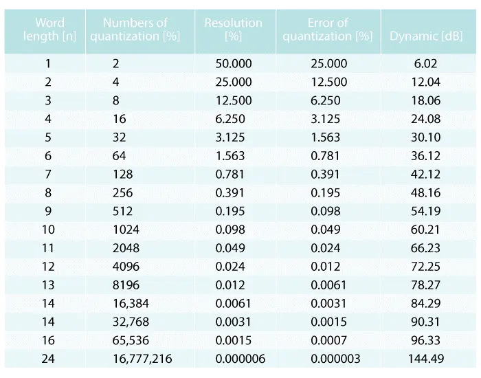
Digital A/D Conversion Digitization converts a continuous signal into one that has discrete values represented with bits. Table 1 shows the characteristics of digitizing signals from 2 bits to 24 bits. The resolution of an A/D converter plays another role in subsequent considerations.

Table 1. The most important parameters of A/D converters and their corresponding values from 2 bits to 24 bits.

Analog Signal Processing When it comes to measurement, Information is not always available as a digital or a frequency signal. The signal amplitude must be decreased to a level suitable for the A/D converter using a voltage divider or increased using an amplifier. The scaling factor of a voltage divider or the gain factor of an operational amplifier is determined by the relative behavior of both resistors. This means that, as long as both resistors behave equally well or equally poorly, the ratio of both resistors is always the same and, consequently, the circuit is decoupled from the properties of the resistors. Resistors, however, never have the same properties. Thus, the ratio of the resistors changes with the ambient temperature, power dissipation, and aging at different film temperatures.

The Effect of TCR Tracking We can use a voltage divider to investigate the effect of the ambient temperature for various temperature coefficients. Forming the complete differential (Equation 1) yields an approximation equation that can estimate the effect of resistance changes resulting from a change in the ambient temperature on the scaling factor.

Equation 1

Assuming that the resolution of the A/D converter corresponds to the permissible error and that both resistors experience the same temperature change, the following approximation equation is obtained by permutation according to the required TCR tracking.

Equation 2

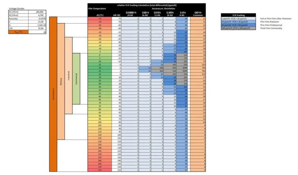
You can use a spreadsheet to estimate the necessary TCR tracking of both resistors in a voltage divider. Your TCR estimation for the resistors can occur with respect to each other as a function of the desired accuracy and over a specified temperature range.

In applications that run in the immediate vicinity of the reference temperature, such as audio, the necessary TCR tracking shows that correspondingly large deviations are allowed between the temperature coefficients. If, however the accuracy requirements are stringent, the use of high grade thin film resistors is recommended at temperature fluctuations of about 10 K. See Table 2.

Table 2. The colors indicate the technology recommendations for resistors extending from thick film resistors, thin film resistors, up to foil resistors.

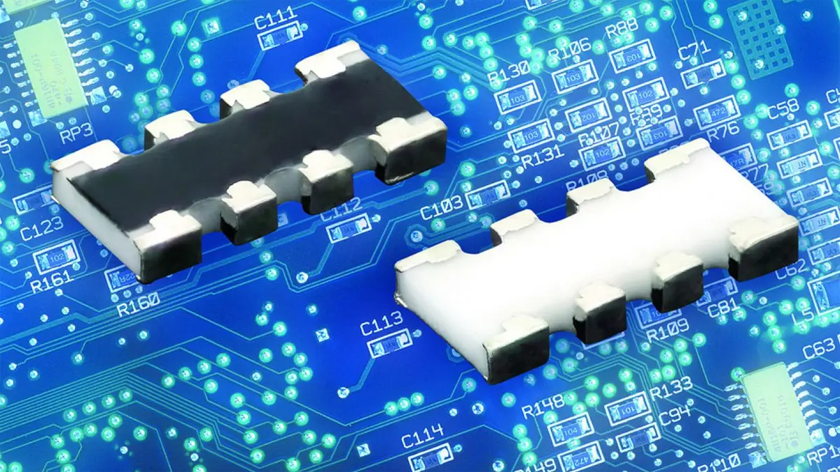
Thin-film chip arrays
Ambient temperature and power dissipation will stress resistors in circuits. In such applications, their resistance value changes at different rates and to a greater or lesser degree depending on the temperature stress and resistive materials used. If resistors age differently due to temperature differences, the scaling factor of a voltage divider will change over the service life. To minimize the costs of quality and calibration, it is necessary for precision measuring engineering to consider resistors having the same temperature coefficients and tolerance pairing. If the desired resistors are fabricated together on one substrate, all the resistors are made of the same resistive material having virtually identical temperature coefficients. Being on the same substrate, the resistors are exposed to the same temperatures over the period of use. As a result, the rate and magnitude of the aging effects are virtually identical.

Figure 1 shows a ceramic substrate for chip array resistors. At least two resistors having the same properties are present on each individual chip array. In this example, we have an array with four individual resistance values.

Figure 1. Ceramic substrate for chip array resistors has four individual resistance values.

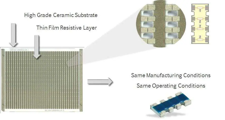
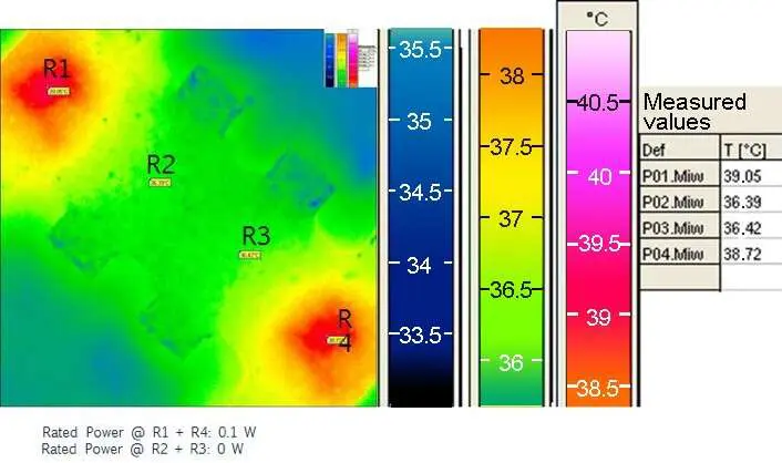
In this case, the influence of temperature on the behavior of the resistor is almost decoupled; the resistors of the chip array are made of the same resistive material and both have a virtually identical temperature coefficient curve because of the common TCR annealing. If the stress placed on the resistors in a chip array differs, the resistors having a higher temperature raise the resistors subjected to less stress to almost the same temperature level. In temperature measurements, a temperature difference of only approximately 3 K was measured between the resistors subject to a full load and those subject to no load (Figure 2).

Figure 2. Resistors R1 through R4 and on the same substrate and made from the same material.

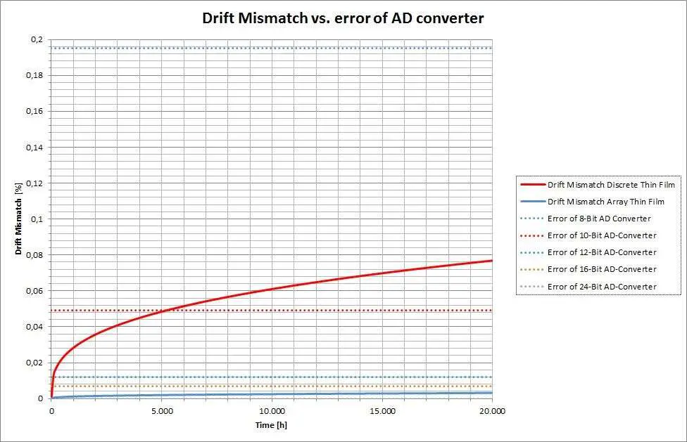
With these results, the change in value of the individual resistors can be estimated using a drift equation and the relative drift change with respect to each resistor can be determined. Figure 3 shows that the drift for discrete thin film resistors used in an 8-bit A/D converter is negligible but, in the case of a 10-bit converter, the LSB exhibits errors after only 5000 hours. With a 12-bit converter and beyond, the use of chip arrays is recommended because the value change of the discrete resistors exceeds the resolution even in the first hours of operation.

Figure 3. Mismatch of a pair of resistors occurs over time

The Effect of Tolerance
It is still worth mentioning that chip arrays can, upon request, be provided with tolerance matching. With this feature, the calibration step at the end of the electronics fabrication line can be eliminated if necessary, increasing the productivity of the SMD line.

Rules for Analog Circuits
Analog signal processing for high resolution digital systems is an exciting and comprehensive task. So that the work proceeds by hand with somewhat more structure, here are a few ground rules for handling resistors or for the development of analog circuits with high digital resolution:

  • Don’t connect voltage dividers directly to the A/D converter. Always connect an impedance converter between them.
  • Keep the TCR effect in mind if the application temperatures deviate from the resistor reference temperature of +20°C.
  • The TCR of a resistor is not linear.
  • The TCR of resistors varies from one production batch to the next.
  • Two production batches may be present in one packaging batch.
  • Something that works in the lab using samples can go awry during the first series production run.
  • To minimize the effect of power dissipation on the drift, use resistors that are as large as possible.
  • Locate resistors in one signal path as close together as possible so that they keep each other warm.
  • Note! Exercise caution with the insulation coordinates.
  • Keep the thermal effect (Seebeck effect) in mind.
  • Avoid resistors that are radially wired; axial designs are preferred.
  • Only position SMD resistors horizontal to the heat flow.
  • Pay attention to the same thermal relationships with the circuit board traces.
  • Use resistors with the longest term stability possible.
  • Pay attention to the drift specifications under continuous loading as per EN 60115-1.
  • The specification of “typical” signifies average values without statistical validation.
  • Use thin film chip arrays if at all possible because these products provide TCR and drift tracking or tolerance matching.

Detecting analog signals and processing them for digital circuitry is used across all industry segments. No one resistor series can satisfy all segment requirements.

featured image: resistor chip array; source: Vishay

Related

Source: EDN

Recent Posts

Common Mode Chokes Selection for RF Circuits in Next-Generation Communication Systems

30.10.2025
7

Capacitor Self-balancing in a Flying-Capacitor Buck Converter

30.10.2025
9

How to Select Ferrite Bead for Filtering in Buck Boost Converter

23.10.2025
42

Power Inductors Future: Minimal Losses and Compact Designs

30.10.2025
50

Percolation Phenomenon: Degradation of Molded Power Inductors in DC/DC Converters

30.10.2025
54

High Energy Density Polymer Film Capacitors via Molecular and Interfacial Design

15.10.2025
35

Over-Voltage Protection Clippers, Clampers, Snubbers, DC Restorers

13.10.2025
42

Silicon Capacitors Market: Shaping the Foundation for Next-Gen Miniaturization Electronics

10.10.2025
90

Enhancing Energy Density in Nanocomposite Dielectric Capacitors

9.10.2025
44

Advances in the Environmental Performance of Polymer Capacitors

8.10.2025
72

Upcoming Events

Nov 4
10:00 - 11:00 PST

Design and Stability Analysis of GaN Power Amplifiers using Advanced Simulation Tools

Nov 4
November 4 @ 12:00 - November 6 @ 14:15 EST

Wirebond Materials, Processes, Reliability and Testing

Nov 6
14:30 - 16:00 CET

Self-healing polymer materials for the next generation of high-temperature power capacitors

View Calendar

Popular Posts

  • Buck Converter Design and Calculation

    0 shares
    Share 0 Tweet 0
  • Boost Converter Design and Calculation

    0 shares
    Share 0 Tweet 0
  • LLC Resonant Converter Design and Calculation

    0 shares
    Share 0 Tweet 0
  • Flyback Converter Design and Calculation

    0 shares
    Share 0 Tweet 0
  • Ripple Current and its Effects on the Performance of Capacitors

    3 shares
    Share 3 Tweet 0
  • MLCC and Ceramic Capacitors

    0 shares
    Share 0 Tweet 0
  • Dual Active Bridge (DAB) Topology

    0 shares
    Share 0 Tweet 0
  • SEPIC Converter Design and Calculation

    0 shares
    Share 0 Tweet 0
  • What is a Dielectric Constant and DF of Plastic Materials?

    4 shares
    Share 4 Tweet 0
  • Flying Capacitors

    0 shares
    Share 0 Tweet 0

Newsletter Subscription


Passive Components Blog

© EPCI - Leading Passive Components Educational and Information Site

  • Home
  • Privacy Policy
  • EPCI Membership & Advertisement
  • About

No Result
View All Result
  • Home
  • Knowledge Blog
  • PCNS

© EPCI - Leading Passive Components Educational and Information Site

This website uses cookies. By continuing to use this website you are giving consent to cookies being used. Visit our Privacy and Cookie Policy.
Go to mobile version