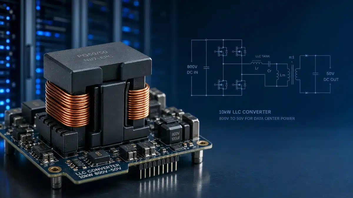
Custom ferrite cores are becoming a practical necessity in high‑power, high‑frequency data center power supplies. This article summarizes a 10 kW LLC transformer design study and explains how integrating the resonant inductance into a custom PQ65‑class core can reduce losses and footprint while keeping manufacturability under control.
Dr. Molina, the CEO of Frenetic, wrote an article specifically for engineers. The article provides guidance on when to abandon standard cores and how to approach a first custom core project within the 800 V to 50 V server PSU range.
Key features and benefits
Custom core integrated transformer
- Integration of transformer and resonant inductance in one magnetic component for a 10 kW, 800 V to 50 V LLC converter with 100 kHz resonant frequency.
- Custom core geometry derived from a PQ65/54 platform with increased effective area to reduce core losses while respecting height and window constraints.
- Target leakage inductance of approximately 40 µH, implemented as intentional leakage between primary and secondary instead of a separate resonant inductor.
- Height limited to about 42 mm to fit dense data center mechanics and allow good coupling to aluminum box or heatsink structures filled with resin.
- Optimized window opening to expose windings for better thermal coupling to cooling surfaces, improving overall thermal performance at higher power density.
From two‑component to merged to fully integrated solution
- Baseline two‑component solution using a PQ65/54 transformer plus a separate PQ40/40 resonant inductor as a conservative, low‑risk starting point.
- Intermediate “mergence” structure adding a half core on top of the transformer to integrate the resonant inductor function while keeping a standard core footprint for manufacturing.
- Fully custom core variant with increased effective area and adapted geometry, enabling higher leakage inductance, lower core losses and reduced height at the expense of custom tooling.
Loss optimization and power density
- Reduction of core losses from about 22 W on standard PQ65/54 to roughly 17 W on the custom core for the same operating conditions and turns count.
- Redistribution of several watts of loss from core to winding to keep total losses in the same range while enabling higher leakage inductance.
- Total transformer losses on the final integrated design around 37.6 W with an estimated hot‑spot temperature of about 86 °C from 25 °C ambient under the 10 kW load.
Typical applications
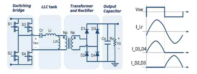
The study is based on a 10 kW LLC converter representative of modern AI and data center power delivery, using 800 V HVDC input and 50 V output compatible with recent server architectures.
- 800 V HVDC data center power shelves for AI and accelerator racks.
- 800 V to 48–54 V front‑end LLC or resonant converters in server PSUs.
- High‑density GaN‑based power stages requiring high switching frequencies and carefully controlled leakage inductance.
- Telecom and industrial rectifiers migrating from traditional 380 V AC front ends to 800 V DC bus architectures.
- Any high‑power LLC stage where integrating the resonant inductor into the transformer is attractive for size, complexity, or cost reasons.
In such designs, transformer geometry, leakage inductance and thermal performance are tightly coupled to mechanical integration in aluminum boxes, cold plates or liquid‑cooled structures, making custom cores increasingly relevant.
Technical highlights
LLC converter specification
- Input voltage: approximately 800 V.
- Output voltage: approximately 50 V.
- Output power: about 10 kW.
- Magnetizing inductance: about 200 µH.
- Resonant inductance: about 40 µH.
- Resonant frequency: about 100 kHz.
- Cooling: aluminum box with resin potting, intended for good interface to a thermal management system.
These values define the basic magnetic stress and leakage requirement for the transformer design.
Baseline two‑component magnetic design
The starting point is a conventional separation of transformer and resonant choke.
- Transformer on PQ65/54 ferrite core (3C95 material) with 16 primary turns and 1 secondary turn, designed for low leakage inductance around a few microhenries and total transformer losses of roughly 30 W.
- Separate resonant inductor on a PQ40/40 core with 22 turns and losses around 12 W.
- Overall approach emphasizes low leakage in the transformer and a discrete resonant choke sized purely for the specified 40 µH.
This architecture is familiar and easy to source with standard cores but occupies more height and volume and complicates thermal management and connection layout.
Merged structure using standard cores
To reduce component count without immediately committing to a fully custom core, a merged structure is studied.
- Main transformer still based on PQ65/54, with an additional half‑core section placed on top to act as the resonant inductor.
- Magnetic circuit arranged so that flux in an intermediate leg cancels, allowing the top half core to carry inductive energy while sharing mechanical structure with the transformer.
- From the mechanical and assembly perspective, this can be treated as a single component with roughly the same pin count as the base transformer, simplifying the BOM.
This approach offers a practical intermediate step when full customization is not yet justified but board space or height are already critical.
Fully custom core: goals and geometry
The final stage is a fully custom core derived from the PQ65/54 outline, with three main goals:
- Integrate the resonant inductor as leakage inductance around 40 µH.
- Improve winding dissipation by exposing the window more to the outside, reducing top and bottom “wings” so windings can couple thermally to an aluminum box or heatsink.
- Increase effective core area to reduce core loss at the same flux waveform.
Two key design constraints are set:
- Maximum overall height around 42 mm to meet mechanical requirements in data center power shelves.
- Target leakage inductance approximately equal to the required resonant inductance so that no extra inductor is needed.
Magnetic design parameters and IEC 60205 use
The custom core process concentrates on three geometric‑magnetic parameters rather than just outer dimensions:
- Effective area Ae: cross‑section of flux‑carrying legs, directly influencing flux density and therefore core loss.
- Effective length Le: mean path length of the magnetic circuit, affecting core reluctance and losses.
- Window area: available space to accommodate copper, insulation, and, if needed, thermal interfaces; smaller window area increases current density and copper loss.
IEC 60205 provides the geometric relationships to compute Ae and Le from core dimensions for standard shapes such as PQ cores. A practical rule applied in the study is that the central leg area is about twice the area of each lateral leg to avoid saturating side legs. Simulation tools such as Frenetic can embed these equations and constraints and flag dimension sets that violate saturation limits or manufacturability rules.
Example: increasing effective area and adjusting window
In the PQ65/54 reference design, the effective area is around 597 mm² with an initial window approximately 35.5 mm by 29 mm. The custom design aims to reduce flux density by at least 10% to cut core losses, knowing that a moderate reduction in Bmax can yield a larger percentage reduction in core loss due to non‑linear material behavior.
Key changes:
- Increase effective area from about 597 mm² to around 733 mm² by enlarging the central and side legs, for example by increasing one external dimension (denoted A) by about 10 mm and then rebalancing other dimensions (such as B, D2, D3) to preserve the window and area ratios.
- Fix the overall height (H1) to about 42 mm, and constrain the minimum leg thickness (for example H1 – H2 section) to around 8 mm to respect ferrite manufacturer guidelines on minimum wall thickness.
- Achieve a revised window around 25 mm by 33 mm, slightly different from the original 35.5 mm by 29 mm but still suitable for the intended windings and thermal approach.
The resulting geometry maintains a practical window while providing a significantly larger effective area, which lowers flux density and core losses at the same number of turns and excitation.
Loss results and leakage inductance implementation
With the increased effective area, calculated core losses drop from roughly 22 W on the standard PQ65/54 to about 17 W on the custom core for the operating conditions used in the study. This reduction frees several watts of loss budget that can be deliberately shifted into copper and leakage generation.
To reach approximately 40 µH leakage inductance:
- The winding arrangement is modified, including adding a spacer between primary and secondary and adjusting interleaving so that coupling is reduced in a controlled manner.
- Proximity loss in the windings increases, but total transformer losses remain acceptable because core losses have been lowered by the larger cross‑section.
The final integrated transformer exhibits total losses around 37.6 W and an expected temperature rise bringing the hottest point to approximately 86 °C from a 25 °C ambient, aligning with typical resin‑potted, forced‑cooled power modules.
Comparative design overview
The three studied options can be summarized as follows (numerical values are indicative and according to the original design discussion and manufacturer data where applicable):
| Design approach | Cores / structure | Separate resonant inductor | Approx. total magnetic losses | Height / volume trend |
|---|---|---|---|---|
| Two‑component standard | PQ65/54 + PQ40/40 | Yes | ~30 W transformer + ~12 W inductor | Tallest, largest footprint |
| Merged structure (standard) | PQ65/54 + half PQ65/54 | Integrated on top | Similar to two‑component, some optimization potential | Height reduced, fewer pieces |
| Custom integrated transformer | Custom PQ65‑derived core | No (Llk ≈ Lres) | ~37.6 W, lower core, higher copper share | Lowest volume, reduced height |
Design‑in notes for engineers
When to move to a custom core
- Consider a custom core once a design based on standard cores cannot simultaneously satisfy height, leakage inductance and loss limits at the desired switching frequency and power density.
- If a separate resonant inductor consumes too much space or causes layout complexity, evaluate integrating the inductance into transformer leakage using winding geometry and core customization.
- When thermal coupling to system cooling hardware requires specific window exposure or flat mounting surfaces that standard cores cannot provide, custom geometry can simplify mechanics and reliability.
Practical design workflow
- Start with a conservative standard‑core design to validate electrical performance and confirm that the resonant tank behaves as intended.
- Incrementally integrate functions: first by a merged structure (for example, adding a half core as an inductor) before committing to a fully new core outline.
- In custom core iterations, treat Ae, Le, and window area as primary design variables, and use IEC 60205 or a dedicated simulator to relate desired magnetic parameters back to external dimensions.
Thermal and mechanical considerations
- Expose windings or copper surfaces where possible to cooling structures; reducing top and bottom wings or adjusting bobbin design can improve resin contact and heatsink bonding.
- Check that minimum ferrite wall thickness and fillet radii meet the vendor’s manufacturing rules to avoid cracking or yield issues.
- Confirm that the final height plus bobbin, insulation and clearances meet system‑level creepage, clearance and mechanical envelope constraints.
Leakage inductance tuning and winding layout
- Treat leakage inductance as an additional design parameter alongside magnetizing inductance, not just a by‑product; spacing, partial interleaving and use of spacers are effective levers.
- Evaluate proximity losses when de‑interleaving windings to increase leakage, especially at 100 kHz and above; simulation tools that model copper losses are highly recommended.
- Keep in mind that moving several watts of loss from core to copper may change the preferred locations for thermal interfaces and sensors in the module.
Vendor collaboration
- Once a candidate custom core geometry is defined and simulated, share detailed drawings and loss estimates with your ferrite supplier for design‑for‑manufacture feedback.
- Use vendor application support to verify that the chosen material grade and geometry align with your flux swing, temperature and frequency regime.
- For long‑term support, consider co‑defining a standard‑like custom family (for example, a “PQ65‑X” variant) that can be reused across several projects in your platform.
Source
This article summarizes and re‑frames information from an original technical article on custom core design for a 10 kW LLC transformer, complemented by standard core geometry and loss considerations according to manufacturer documentation and IEC 60205.