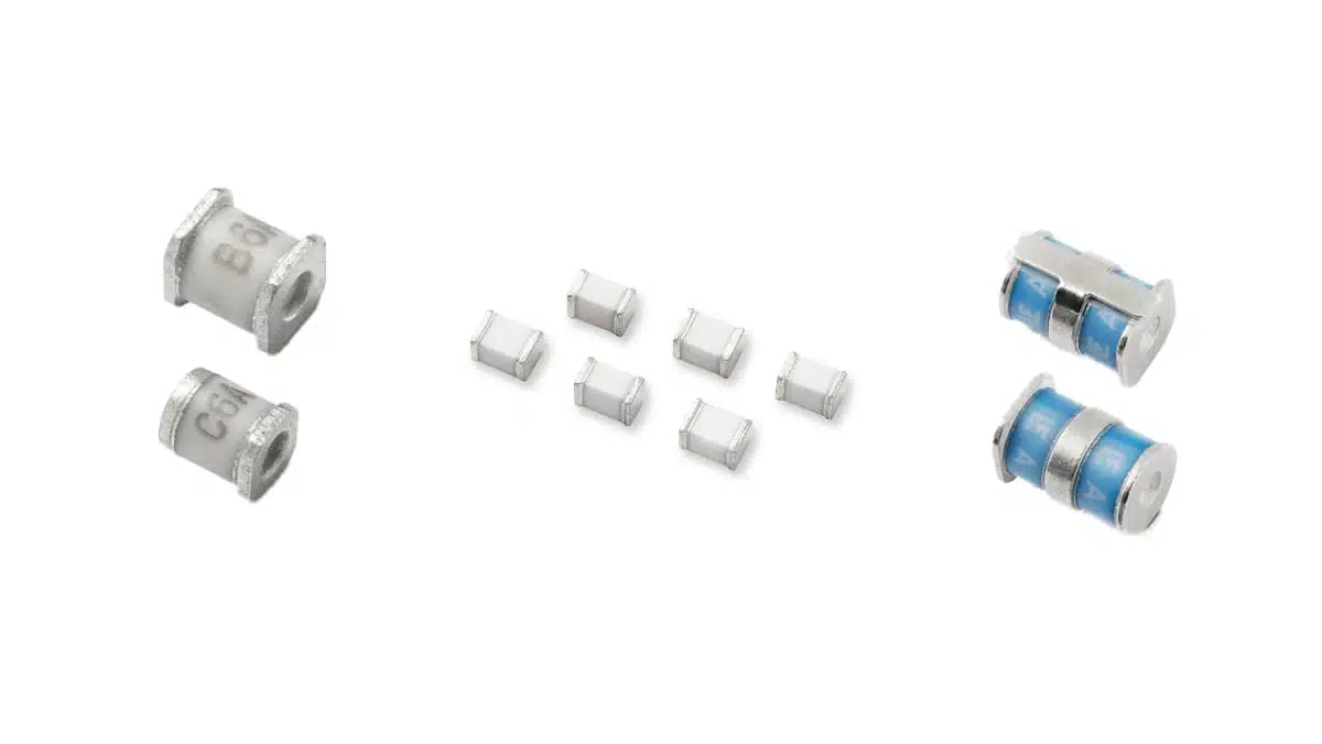
This article summarizes how GDT (Gas Discharge Tube) work, how they differ from other surge protectors, and what design engineers should watch when specifying them into new designs.
Gas discharge tubes are crowbar‑type surge over-voltage protection components that use a controlled gas discharge to divert high‑energy transient currents away from sensitive circuitry. They offer very high surge capability, low leakage, and extremely low capacitance, making them a key building block in telecom, industrial, and AC power surge protection.
Key Takeaways
- Gas discharge tubes (GDTs) provide effective surge protection by diverting high-energy currents from sensitive circuits.
- GDTs function as high-impedance insulators until voltage exceeds a breakdown level, turning into conductive plasma arcs.
- They possess high surge current capability, low off-state capacitance, and high insulation resistance, making them ideal for telecom and industrial applications.
- Engineers should select GDTs based on breakdown voltage, follow-on current risks, and coordination with MOVs or TVS devices for optimal performance.
- Common applications include telecommunications, AC power line SPDs, and high-voltage DC systems, ensuring robust and reliable surge protection.
What a GDT gas discharge tube is and why it matters
A gas discharge tube is a hermetically sealed ceramic component filled with inert gas and equipped with two or three electrodes. Under normal conditions it behaves like a very high‑impedance insulator with giga‑ohm leakage and picofarad‑level capacitance. When the voltage across its terminals exceeds a defined breakdown level, the gas ionizes and the device switches into a low‑impedance plasma arc state, shunting surge current safely to ground or between lines according to the chosen topology.
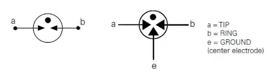
GDT Symbols
Compared to purely solid‑state protectors, GDTs can handle very large 8/20 µs surge currents in a compact footprint, and they introduce negligible loading to high‑frequency or high‑speed lines in their off‑state. At the same time, they must be coordinated carefully with the rest of the circuit because the low on‑state voltage can lead to follow‑on current if the system can sustain the arc. Hybrid solutions that combine GDTs with MOVs or TVS components are therefore common in modern surge protection architectures.
Key features and benefits
- High surge current capability
Many GDT families support nominal discharge currents in the 5 kA to 40 kA range on standardized 8/20 µs waveforms, with maximum ratings even higher for single pulses. This makes them suitable as the first line of defense in lightning‑prone or high‑energy industrial environments. - Very low off‑state capacitance
Typical capacitance values are in the sub‑pF to a few pF range depending on package and breakdown rating, which minimizes insertion loss and distortion on RF, xDSL, or other high‑frequency interfaces. Low capacitance is a key reason why GDTs remain popular in telecom line cards and RF front ends. - Extremely high insulation resistance
Off‑state insulation resistance commonly exceeds 1 GΩ and can reach tens of giga‑ohms, reducing leakage currents from line to ground and helping designers meet safety and standby consumption targets. - Voltage‑dependent crowbar behavior
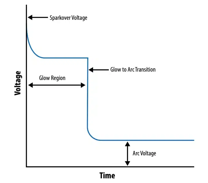
A GDT behaves as a voltage‑triggered switch: when the applied voltage exceeds the DC breakdown (spark‑over) level, it rapidly transitions into a conductive state with a low arc voltage. Once the surge has decayed and the current falls below the holdover level, it resets back to its insulating state. - 2‑electrode and 3‑electrode options
Two‑electrode types are used for line‑to‑ground or line‑to‑line protection, while three‑electrode designs allow simultaneous, symmetrical protection of differential pairs, ensuring that both lines reference the same potential during a surge event. - Hybrid integration possibilities
Recent developments integrate a MOV and a GDT in series in a single component, combining the high surge capability and low leakage of the tube with the clamping characteristics of the varistor. This improves energy handling and extends lifetime compared to stand‑alone MOV solutions in many AC power applications.
Technical highlights
From a design point of view, several parameters define how a GDT behaves in real circuits.
Breakdown characteristics
The most fundamental parameters are the DC spark‑over voltage and the impulse spark‑over voltage.
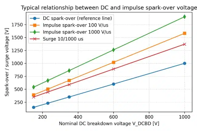
- DC spark‑over is measured with a slowly rising DC or ramp waveform and defines the nominal voltage at which the gas begins to ionize under quasi‑static conditions.
- Impulse spark‑over is measured with fast waveforms such as 1.2/50 µs and typically exceeds the DC value because of statistical time lag and dynamic effects inside the gas.
For power line protection, design guides often recommend setting the minimum DC breakdown level to at least the peak of the highest expected operating voltage plus an additional guard band. For example, on a 120 V RMS line, the peak is approximately 120×1.414, and the selected GDT DC breakdown should be higher than this value according to manufacturer application notes.
Discharge current and energy ratings
GDTs are characterized by nominal and maximum discharge current ratings on standardized waveforms, most commonly 8/20 µs impulses.
- The nominal discharge current defines the surge amplitude the tube can withstand repeatedly for a specified number of pulses.
- The maximum discharge current is a higher single‑shot rating used to size devices for worst‑case lightning or switching events.
Energy handling capabilities are sometimes specified in joules, especially for hybrid MOV–GDT components. For instance, hybrid series for AC mains can absorb several hundred joules per 8/20 µs surge, with different disk diameters covering ranges from roughly 200 J up to around 490 J for the largest types, according to manufacturer datasheets.
Follow‑on current and arc voltage
Once the GDT has fired, its arc voltage drops to a relatively low level compared to the circuit voltage. Because the device is essentially a triggered short circuit, any sustained current is determined by the source voltage and impedance. If the system can supply a current above the holdover level, the GDT will remain in conduction, which can overheat both the tube and upstream components. For this reason:
- Follow‑on current capability is an important application‑level parameter even if it is not always listed as a fixed datasheet number.
- Hybrid GDT–MOV arrangements use the MOV to limit the voltage and help extinguish the arc once the surge has decayed.
Capacitance and insulation resistance
Off‑state capacitance in the sub‑pF to low‑pF range is critical for maintaining signal integrity on high‑speed and RF lines. Application notes describe dedicated measurement setups to obtain accurate capacitance values at the relevant frequency, especially for very low‑capacitance telecom GDTs. In parallel, minimum insulation resistance values in the giga‑ohm range ensure negligible leakage in normal operation.
Standards and testing
GDTs for telecom and low‑voltage networks are often tested according to ITU‑T K.12 and related surge recommendations. Devices intended for AC mains SPDs are designed to support compliance with UL 1449, IEEE C62.41, and similar surge immunity and safety standards when integrated into suitable surge protective devices. Manufacturers provide application notes with typical test circuits using 1.2/50 µs voltage and 8/20 µs current waveforms to verify proper coordination.
Representative parameter ranges table
The following table gives indicative parameter ranges as published for contemporary GDT and hybrid series; exact values are according to manufacturer datasheets.
| Parameter | Typical telecom GDT | AC mains hybrid MOV–GDT | High‑voltage GDT series |
|---|---|---|---|
| DC breakdown | ~75 V to a few hundred volts | 50 V AC to ~750 V AC operating voltage | 1000 V to 2000 V DC breakdown |
| Nominal 8/20 µs current | Few kA | 6 kA (14 mm) to 10 kA (20 mm) | Up to 40 kA nominal |
| Maximum 8/20 µs current | Higher single‑pulse ratings | Energy up to ~490 J, single pulse | Up to around 60 kA maximum |
| Capacitance | Sub‑pF to a few pF | MOV‑dominated, GDT helps keep leakage near zero | Low to moderate, application‑dependent |
| Operating temperature | Typically −40 °C to +85 °C or +105 °C | −40 °C to +105 °C | According to manufacturer datasheet |
Typical applications
GDTs are used across a wide range of circuits wherever high‑energy surges must be controlled without compromising normal operation.
- Telecommunications and data lines
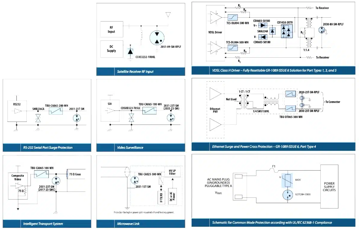
Protection of copper telecom interfaces, xDSL ports, MDF blocks, RF antennas, and base station feeders. Here, low capacitance and balanced protection are critical to maintain line performance while meeting surge immunity requirements such as ITU‑T K.12 and related standards. - AC power line surge protective devices (SPDs)
Integration into Type 1/2 surge protective devices for residential, commercial, and industrial AC mains. High‑energy GDTs rated to tens of kiloamps on 8/20 µs waveforms can be coordinated with MOVs or other elements to meet UL 1449 and IEEE C62.41 classes. - Industrial control and instrumentation
Protection of I/O modules, sensor loops, alarm systems, and field‑bus networks exposed to lightning or switching surges through long cable runs. GDTs help improve system robustness while keeping leakage low in high‑impedance measurement circuits. - Combined MOV–GDT surge modules
AC line protection where a hybrid component combines GDT and varistor in a single leaded package. Such devices reduce leakage current to nearly zero under normal conditions while providing high surge current and energy handling capability in a compact form factor. - High‑voltage DC and power conversion
New high‑voltage GDT families are aimed at DC bus protection, power converters, and other high‑energy systems with DC breakdown voltages in the kilovolt range and surge ratings up to around 60 kA on 8/20 µs impulses, according to manufacturer datasheets.
Example application table
The table below summarizes typical use cases and design priorities for different GDT classes according to manufacturer documentation.
| GDT class | Typical use case | Key design priorities |
|---|---|---|
| Low‑capacitance telecom | xDSL, RF, antenna ports | Sub‑pF capacitance, ITU‑T K.12 compliance |
| Standard signal line | Industrial I/O, alarm loops | Balance between breakdown level and surge rating |
| AC mains SPD GDT | Type 1/2 surge protectors | High 8/20 µs current rating, coordination with MOV |
| Hybrid MOV–GDT component | Board‑level AC input protection | Very low leakage, high energy, compact footprint |
| High‑voltage GDT | HV DC bus, power systems | kV‑range breakdown, 40–60 kA surge capability |
Design‑in notes for engineers
- Select breakdown voltage with margin
Choose the minimum DC breakdown voltage so that it exceeds the highest expected peak operating voltage, including tolerances and temporary overvoltages. For AC mains, design notes often start from the RMS line voltage, convert to peak, and then add a safety margin before picking the closest available GDT rating. - Analyze follow‑on current and coordination
Check whether the protected system can sustain significant current at the GDT arc voltage. If so, plan for series impedance and/or a secondary protector such as a MOV or TVS diode that will clamp the voltage and allow the GDT to extinguish once the surge passes. - Pay attention to surge environment and test class
Determine the expected surge profile based on standards such as IEEE C62.41 or ITU‑T recommendations and select GDTs with nominal and maximum discharge current ratings exceeding those levels with suitable margin. Consider multi‑pulse endurance when dimensioning for repetitive events rather than rare extremes. - Minimize parasitics in PCB layout
Place the GDT close to the entry point of the line and ensure a low‑impedance path to the reference node (ground or other line). Avoid long, narrow traces that add inductance and can degrade the effective clamping performance during fast surges. - Consider 3‑electrode devices for differential pairs
For twisted‑pair or differential signal lines, three‑electrode GDTs provide symmetrical protection for both conductors within a shared gas chamber, improving balance and helping to avoid residual transverse voltages during surges. - Observe thermal and mechanical constraints
Verify operating temperature range and ensure adequate spacing and creepage distances on the PCB for the selected breakdown voltage class. For high‑energy or high‑voltage parts, mechanical mounting and enclosure design should also consider venting and safe failure behavior as described in the manufacturer’s application notes. - Use manufacturer guidance for testing
Follow recommended test circuits for verifying spark‑over voltage, insulation resistance, and surge behavior. Dedicated notes describe how to measure capacitance accurately, how to subject devices to standardized surge impulses, and how to interpret degradation or failure indicators after testing.
Summary
Gas discharge tubes are crowbar‑type surge protection components that use a controlled gas discharge to divert high‑energy transients away from sensitive circuitry while adding almost no capacitance or leakage in normal operation. By understanding their breakdown behaviour, surge current and energy ratings, and follow‑on current risks, design engineers can use GDTs as a robust first line of defense in telecom, industrial, RF, and AC mains surge protection architectures. The article reviews key parameters, representative ranges, and typical application classes, and it outlines practical design‑in notes and a step‑by‑step selection workflow to support reliable implementation.
Conclusion
Gas discharge tubes remain highly relevant wherever high surge capability, low leakage, and very low capacitance are required, especially on exposed lines and interfaces that must still meet demanding signal integrity targets. When engineers correctly select breakdown voltage, dimension surge current and energy ratings against the expected environment, and coordinate GDTs with MOVs or TVS components, GDT‑based stages can significantly improve system robustness and standards compliance. Careful attention to follow‑on current, PCB layout, and verification testing ensures that GDT protection performs as intended over the full service life of the equipment.
GDT gas discharge tubes FAQ
A gas discharge tube (GDT) is a hermetically sealed ceramic component filled with inert gas and equipped with two or three electrodes that behaves as a high impedance insulator in normal operation and switches into a low impedance plasma arc when its breakdown voltage is exceeded. This crowbar behaviour allows the GDT to divert high energy surge currents safely away from sensitive circuitry and makes it a key building block in telecom, industrial and AC mains surge protection devices.
Compared with MOV and TVS components, GDTs offer much higher surge current capability on 8/20 µs waveforms, extremely low off state capacitance in the sub pF to few pF range and very high insulation resistance in the giga ohm range. However the low arc voltage of a fired GDT can lead to follow on current if the system can sustain the arc, so GDTs are often coordinated with MOVs or TVS diodes in hybrid protection schemes.
Gas discharge tubes are widely used on copper telecom and data lines, RF antennas, xDSL ports, industrial I/O and alarm loops, as well as in Type 1 and Type 2 AC power line surge protective devices. High energy and high voltage GDT families are also applied on high voltage DC buses and power converters where kV range breakdown voltages and surge ratings up to several tens of kA are required.
Important selection parameters include DC and impulse spark over voltage, nominal and maximum discharge current ratings on standard 8/20 µs waveforms, energy handling capability, off state capacitance, insulation resistance and operating temperature range. Designers should choose the breakdown voltage with sufficient margin above the highest expected peak operating voltage and verify that surge current and energy ratings exceed the required test classes defined in standards such as ITU T K.12, UL 1449 and IEEE C62.41.
To avoid dangerous follow on current after a GDT fires, designers should evaluate the source impedance and prospective current at the GDT arc voltage and add series impedance where necessary. Hybrid GDT–MOV arrangements or secondary TVS stages can be used so that the MOV or TVS clamps the voltage and helps extinguish the arc once the surge decays, preventing the tube from remaining in continuous conduction.
Low capacitance GDTs with sub pF to a few pF capacitance minimize insertion loss and distortion on RF, xDSL and other high frequency lines. This allows designers to meet surge immunity requirements while preserving signal integrity on telecom interfaces, RF front ends and antenna ports where conventional MOV based surge protectors would introduce excessive parasitic capacitance.
How to design in a GDT surge protection stage
- Define surge environment and standards
Start by identifying the relevant surge environment and compliance standards for your application, such as ITU T K.12 for telecom lines or UL 1449 and IEEE C62.41 for AC power line SPDs. Determine the required test waveforms, surge current levels and number of pulses so you can size the GDT nominal and maximum discharge current ratings with adequate margin.
- Determine operating voltage and breakdown margin
Next, determine the highest continuous operating voltage and any temporary overvoltage the line may experience, including tolerances. For AC mains, convert the RMS line voltage to its peak value and then choose a GDT DC breakdown rating that is comfortably above this peak while still low enough to protect downstream components.
- Select GDT type and topology
Choose between 2 electrode and 3 electrode GDTs depending on whether you protect a single conductor to ground or a differential pair that requires symmetrical protection. Select a product family that offers the required breakdown voltage range, surge current capability and environmental ratings for telecom, industrial control, AC mains SPD or high voltage DC bus applications.
- Check surge current and energy ratings
From the manufacturer datasheet, verify that the nominal and maximum 8/20 µs discharge current ratings exceed the surge currents defined by your target test classes. For hybrid MOV–GDT solutions, also check the specified energy handling in joules per surge and ensure that device ratings cover worst case lightning or switching events with suitable design margin.
- Analyze follow on current and coordination
Evaluate the prospective current that the system can deliver at the GDT arc voltage and verify whether it may exceed the device holdover current. If follow on current is a risk, include series impedance and coordinate the GDT with secondary protectors such as MOVs or TVS diodes so that the arc can extinguish cleanly once the surge has decayed.
- Verify capacitance, leakage and temperature ratings
For high speed or RF lines, confirm that the specified off state capacitance of the chosen GDT is compatible with your signal integrity requirements. Check minimum insulation resistance in the giga ohm range and operating temperature range, typically from −40 °C up to +85 °C or +105 °C, to ensure reliable long term operation in the target environment.
- Optimize PCB placement and test
Place the GDT close to the line entry point and provide a short, low inductance path to the reference node or ground to minimize parasitic impedance during fast surges. Build a prototype and use the manufacturer recommended test circuits with standardized 1.2/50 µs voltage and 8/20 µs current waveforms to verify spark over voltage, clamping performance, follow on current behaviour and any device degradation after testing.
Source
This article is based on information from manufacturer technical libraries, application notes, product overviews, and press releases on gas discharge tubes and hybrid GDT–MOV surge protection devices. Exact numerical values and ratings are according to the latest datasheets and product documentation made available by the respective manufacturers.
Further Read
References
- Bourns Gas Discharge Tubes Technical Library
- Bourns GDT Surge Arrestors – product overview
- Bourns Gas Discharge Tubes Brochure
- Bourns High Voltage Gas Discharge Tube press material
- Bourns High‑Voltage, High‑Energy GDT Series press release
- Littelfuse Gas Discharge Tube overview
- Littelfuse Squared GDT series
- Littelfuse Application Note – Combining GDTs and MOVs for Surge Protection of AC Power Lines
- Application of Gas Discharge Tubes in Power Circuits
- TDK Electronics – Combined varistor and gas discharge tube (G series) press information