Passive Components Blog
No Result
View All Result
  • Home
  • NewsFilter
    • All
    • Aerospace & Defence
    • Antenna
    • Applications
    • Automotive
    • Capacitors
    • Circuit Protection Devices
    • electro-mechanical news
    • Filters
    • Fuses
    • Inductors
    • Industrial
    • Integrated Passives
    • inter-connect news
    • Market & Supply Chain
    • Market Insights
    • Medical
    • Modelling and Simulation
    • New Materials & Supply
    • New Technologies
    • Non-linear Passives
    • Oscillators
    • Passive Sensors News
    • Resistors
    • RF & Microwave
    • Telecommunication
    • Weekly Digest

    Binder Hybrid Connector Simplifies One Cable Automation

    Tapped Inductor Buck Converter Fundamentals

    TAIYO YUDEN Releases Mini Metal Power Inductors

    Molecular Memristor Shows Record 145 kH Emergent Inductance

    Planar vs Conventional Transformer: When it Make Sense

    Researchers Propose Next‑Gen Compact Memory Using Ultra-thin Ferroelectric Capacitors

    Nichicon ADN Automotive Hybrid Aluminum Capacitors Now Available in EMEA

    Wk 19 Electronics Supply Chain Digest

    Electrocaloric Multilayer Capacitors: Towards Quiet, Solid‑State Cooling Around Room Temperature

    Trending Tags

    • Ripple Current
    • RF
    • Leakage Current
    • Tantalum vs Ceramic
    • Snubber
    • Low ESR
    • Feedthrough
    • Derating
    • Dielectric Constant
    • New Products
    • Market Reports
  • VideoFilter
    • All
    • Antenna videos
    • Capacitor videos
    • Circuit Protection Video
    • Filter videos
    • Fuse videos
    • Inductor videos
    • Inter-Connect Video
    • Non-linear passives videos
    • Oscillator videos
    • Passive sensors videos
    • Resistor videos

    Tapped Inductor Buck Converter Fundamentals

    Planar vs Conventional Transformer: When it Make Sense

    Modeling Fringing Field Losses in Inductors & Transformers

    Why Power Inductors Use a Ferrite Core With an Air Gap

    Transformer-Based Power-Line Harvester Magnetic Design

    Thermal Modeling of Magnetics

    Standard vs Planar LLC transformers Comparison for Battery Chargers

    How Modern Tools Model Magnetic Components for Power Electronics

    Advanced Loss Modeling for Planar Magnetics in the Frenetic Planar Tool

    Trending Tags

    • Capacitors explained
    • Inductors explained
    • Resistors explained
    • Filters explained
    • Application Video Guidelines
    • EMC
    • New Products
    • Ripple Current
    • Simulation
    • Tantalum vs Ceramic
  • Knowledge Blog
  • DossiersNew
  • Suppliers
    • Who is Who
  • PCNS
    • PCNS 2025
    • PCNS 2023
    • PCNS 2021
    • PCNS 2019
    • PCNS 2017
  • Events
No Result
View All Result
Passive Components Blog
No Result
View All Result

How Clock Oscillator Works

23.11.2023
Reading Time: 4 mins read
A A

This article based on KYOCERA technical note explains what is a clock oscillator and how it works.

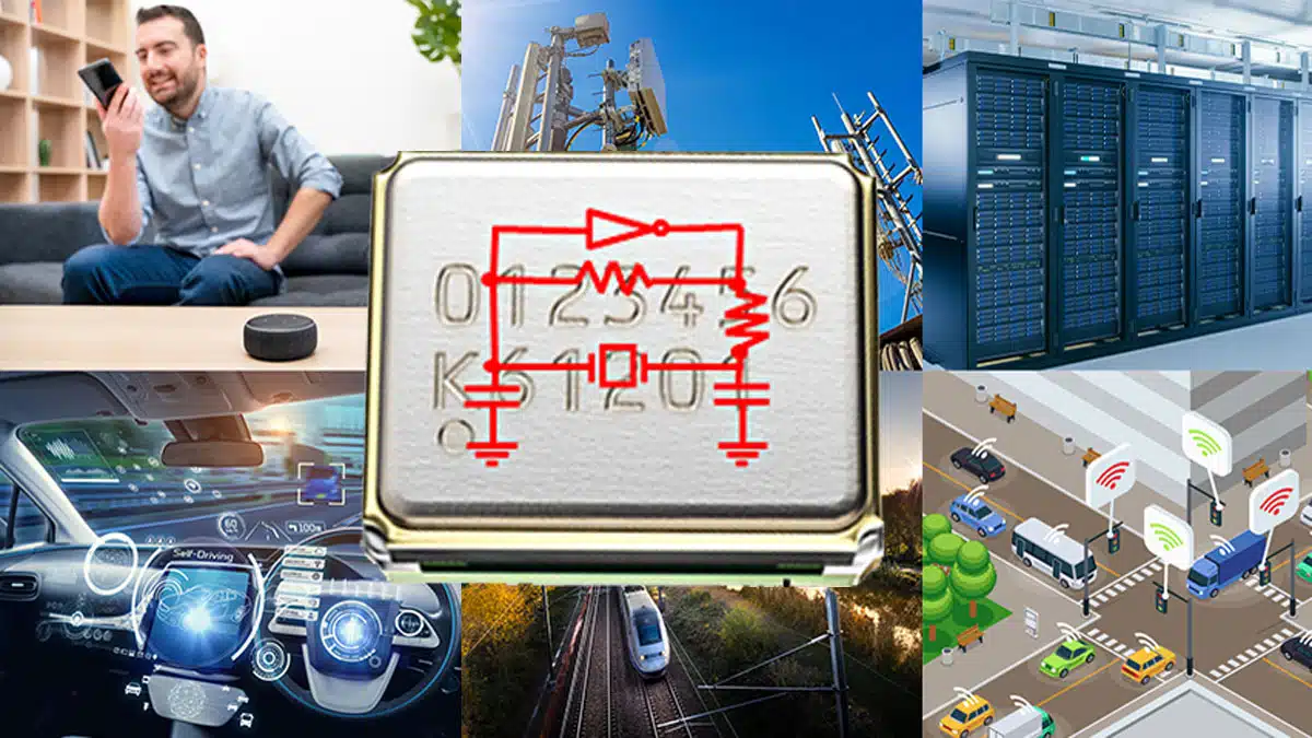
Crystal devices are used in a variety of electronic devices essential to our lives, from consumer electronics, automobiles, and communications equipment to transportation infrastructure, FA equipment, and medical equipment. Among them, clock oscillators are easy to work with and particularly useful as frequency sources.

RelatedPosts

KYOCERA 10 µF 0201 MLCC Brings High‑Capacitance into Mobile Designs

KYOCERA AVX Extends MLV Varistors for 48V Automotive Protection

Kyocera Developed Multilayer Ceramic Core Substrate for AI Packages

How Crystal Units Work

Before getting into clock oscillators, let’s first give some background about “crystal units.”

A crystal unit is a “passive component” – meaning it does not operate on its own. Therefore, it controls various electronic devices using the piezoelectric phenomenon that causes strain and vibration when voltage is applied to a crystal.

In order to convert the mechanical vibration generated by the piezoelectric phenomenon into an electrical signal and obtain the frequency, an oscillation circuit that can continuously produce the frequency by oscillating a vibrator is required.

What are passive parts?

Components that consume, store, and release electrical energy supplied from the outside. Examples include resistance, capacitors, coils, etc. In contrast, “active components” are capable of amplifying, rectifying, and converting supplied electrical energy. Examples of these include transistors, integrated circuits, etc.

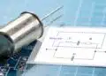
How to Make a Crystal Unit Oscillate

In order to generate oscillations, a matching process is required to match the oscillation circuit and the Rf , Rd , Cd, Cg  of the quartz crystal to suitable values for oscillation.

Oscillator with crystal unit circuit schematic

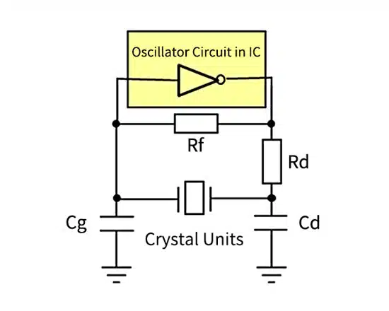
If the matching is insufficient, system failures such as frequency shift, abnormal oscillation, output level drop, and oscillation stop may occur.

  • Rf=Feedback Resistor
  • Rd=Power Limiting Resistor
  • Cd,Cg=Load Capacity

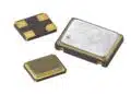
What is a Clock Oscillator?

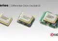
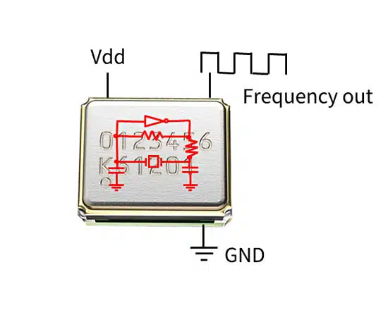
Clock oscillators are designed by crystal device manufacturers to provide customers with the best possible oscillation state by combining an oscillation circuit and a crystal resonator into a package.

By simply applying voltage, you get a clock signal of the desired frequency.

What is a Clock Signal?

A periodic electrical signal that “ticks” at regular intervals. This allows the timing of actuation to be synchronized among multiple electronic circuits.

Main Applications of Clock Oscillators

As noted above, clock oscillators are used in various electronic devices essential to our lives, from home appliances, automobiles, and communications equipment to transportation infrastructure, FA equipment, and medical equipment.

If you know what frequency you need, you can search for the optimal clock oscillator in the vendor PN list.

Related

Source: KYOCERA

Recent Posts

Murata Introduces Crystal and NTC Set for Automotive UWB Timing

30.4.2026
31

Equivalent Circuit Constants of Crystal Units Explained

26.3.2026
58

Kyocera Releases 30fs Jitter Differential Clock Oscillator

10.3.2026
28

Würth Elektronik IQD Awarded by EcoVadis Gold Sustainability Medal

4.3.2026
5

Kyocera Releases Ultra-Compact Low Voltage Clock Oscillators

12.11.2025
69

Murata Releases In-vehicle Compact Crystal in 2016 Size

23.7.2025
23

Minimization of Crystal Oscillator Cosmic Radiation Effects

28.4.2025
58

Vishay Unveils New SMD Crystals and Oscillators

7.1.2025
73

Murata Unveils Innovative Timing Device with Exceptional Accuracy

18.11.2024
84

Upcoming Events

May 19
16:00 - 17:00 CEST

Designing Qi2 Wireless Power Systems: Practical Development and EMC Optimization

Jun 2
16:00 - 17:00 CEST

Calculation, Simulation and Measurement of 800V EMC Filters

Jun 16
16:00 - 17:00 CEST

EMC with EMC – EMC‑compliant design with electromechanical connectors

View Calendar

Popular Posts

  • Buck Converter Design and Calculation

    0 shares
    Share 0 Tweet 0
  • Boost Converter Design and Calculation

    0 shares
    Share 0 Tweet 0
  • Flyback Converter Design and Calculation

    0 shares
    Share 0 Tweet 0
  • LLC Resonant Converter Design and Calculation

    0 shares
    Share 0 Tweet 0
  • MLCC and Ceramic Capacitors

    0 shares
    Share 0 Tweet 0
  • Dual Active Bridge (DAB) Topology

    0 shares
    Share 0 Tweet 0
  • Capacitor Charging and Discharging

    0 shares
    Share 0 Tweet 0
  • What Electronics Engineer Needs to Know About Passive Low Pass Filters

    0 shares
    Share 0 Tweet 0
  • Ripple Current and its Effects on the Performance of Capacitors

    3 shares
    Share 3 Tweet 0
  • MLCC Case Sizes Standards Explained

    0 shares
    Share 0 Tweet 0

Newsletter Subscription


Passive Components Blog

© EPCI - Leading Passive Components Educational and Information Site

  • Home
  • Privacy Policy
  • EPCI Membership & Advertisement
  • About

No Result
View All Result
  • Home
  • Knowledge Blog
  • PCNS

© EPCI - Leading Passive Components Educational and Information Site

This website uses cookies. By continuing to use this website you are giving consent to cookies being used. Visit our Privacy and Cookie Policy.
Go to mobile version