The article introduces basic principles of inductive components – Magnetism, Ampère’s Law and Magnetic Fields Strength.
Magnetism
The basis for understanding inductors is provided by magnetism and a few fundamental electromagnetic field laws, revealing clear and fundamental knowledge of inductors and ferrites. The most important phenomena and laws will still perhaps be there from physics lessons:
- Every magnet has a north and south pole (The earth is an enormous magnet!)
- If an existing magnet is divided, a new one is created. The magnet so created also has a north and south pole. This division can be performed down to the molecular level without losing the magnetic effect.
- Every magnet is surrounded by a magnetic field, which is represented by the field line model.
- Magnetic field lines are closed. They neither beginning nor end. There are magnetizable materials (e.g. iron) and non-magnetizable materials (e.g. aluminum).
- The following analysis concerns a class of magnetizable materials, the ferromagnetic materials.
Ferromagnetic materials
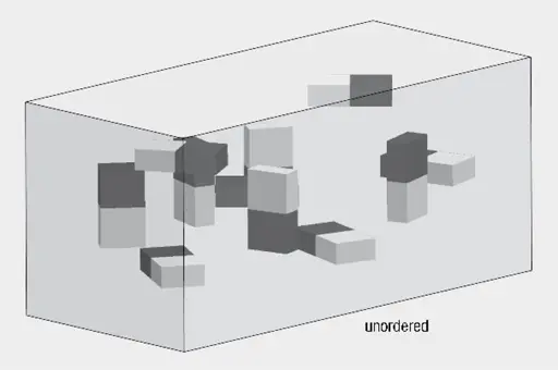
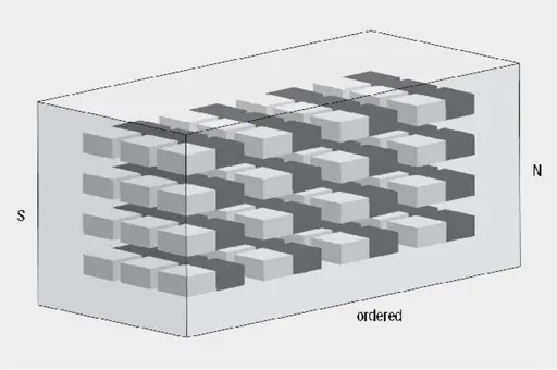
Every magnetic material is composed of a finite number of the smallest elementary magnets, configured randomly in the unmagnetized state. These orientate themselves under the influence of an external magnetic field.
If all elementary magnets are oriented in the magnetic field, one speaks of saturation of the material.Once the externally applied magnetic field is removed, two effects can occur:
- The material becomes nonmagnetic once again: One speaks of a soft magnetic material
- The material remains magnetic: One speaks of a hard magnetic material
Ampère’s Law and Magnetic Field Strength
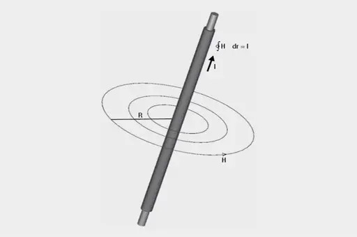
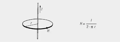
A magnetic field is created around an electric conductor passing a current. This magnetic force field is a vector quantity perpendicular to the generating current. Field lines represent the magnetic force field. For a current carrying conductor, these form closed concentric circles.
Integrating in a counter clockwise direction along a field line, the H and each distance increment (dr) are always in the same direction. A complete circulation provides the magnetic boundary potential is shown in Figure 3.
If several conductor currents pass through the enclosed area, the sum of the currents must be on the right side of the equation (observing their directional signs):
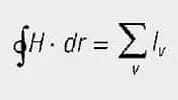
The magnetic field is measured by means of the magnetic field strength H and is defined by the currents generated by the field.
Biot-Savart Law
The field strength of any conductor configuration may be determined from the Biot-Savart Law:
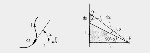
Accordingly, the small section (ds) of the conductor carrying current (I) makes the contribution:

(alpha) is the angle between the direction of the line element (ds) and its connection (r) to the point (P) at which the field strength (dH) exists.
Magnetic Field Strength H
The magnetic field strength (H) results from integrating over the entire length of the conductor.
The contour integral of H along a closed line is equal to the total current through the area across this closed path. The magnetic field strength is given by the total current through the surface enclosed by the magnetic field line and the length of this field line.
If it is assumed that the same currents flow in N discrete conductors, as in the case of a coil, the equation simplifies to:
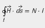
N = number of conductors within the closed path l
I = current per conductor
The unit of magnetic field strength (H) is A/m.
Examples:
Straight current conductor
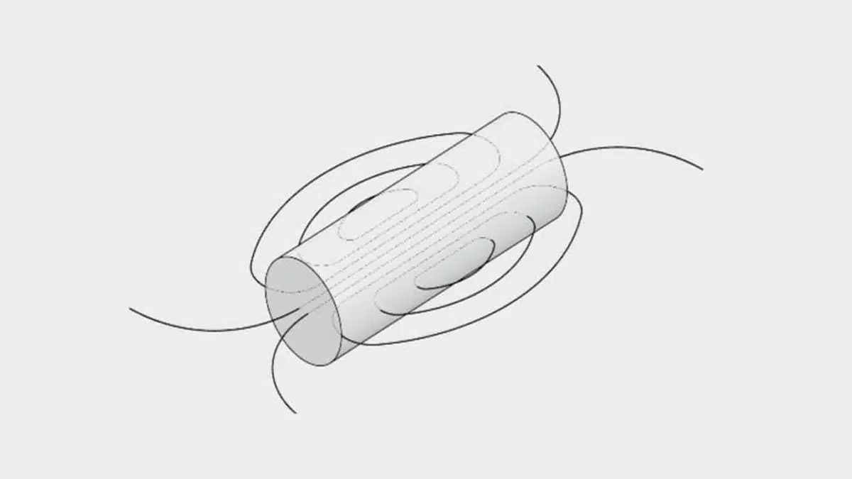
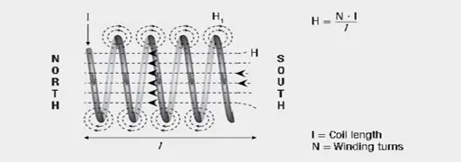
Long solenoid
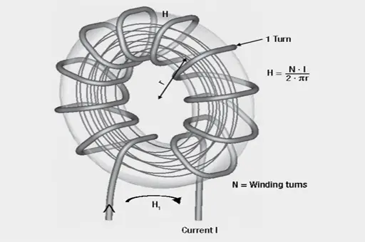
Toroidal coil
The Figure 6. illustration shows the size of the magnetic field strength (H) inside a long solenoid to be dependent on the current I, the coil length l and the winding turns N.
Example calculation :
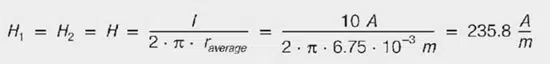
Ferrite sleeve 742 700 9 on a conductor with DC current of I = 10A
Sleeve dimensions:
da = 17.5 mm; di = 9.5 mm; l = 28.5 mm
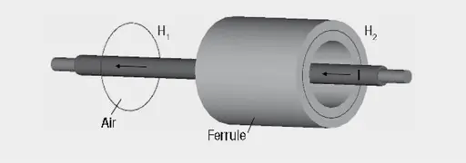
Question:
What is a field strength H1 in air and field strength H2 in ferrule (centered conductor) on Figure 8.?
Answer:
The field strengths H1 in air and H2 in the ferrule are the same size. The field strength is given by: