Passive Components Blog
No Result
View All Result
  • Home
  • NewsFilter
    • All
    • Aerospace & Defence
    • Antenna
    • Applications
    • Automotive
    • Capacitors
    • Circuit Protection Devices
    • electro-mechanical news
    • Filters
    • Fuses
    • Inductors
    • Industrial
    • Integrated Passives
    • inter-connect news
    • Market & Supply Chain
    • Market Insights
    • Medical
    • Modelling and Simulation
    • New Materials & Supply
    • New Technologies
    • Non-linear Passives
    • Oscillators
    • Passive Sensors News
    • Resistors
    • RF & Microwave
    • Telecommunication
    • Weekly Digest

    PCNS 2025 Final Program Announced!

    DigiKey Expands Inventory with Over 32,000 Stocking NPIs in Q2 2025

    YAGEO Offers High-Performance Diplexers for Dual-Band Wi-Fi 6E/7Integration

    European Components Distribution (DMASS) Faces Continued Decline in Q2 2025

    TDK Announced Wide Frequency Automotive Wirewound POC Inductors

    Bourns Released Rugged, High-Power TO-247 Thick Film Resistor

    Bourns Announced Shielded Power Inductor with High Saturation and Low Radiation

    Würth Elektronik Expands MagI³C with Variable Step-Down Modules

    KYOCERA AVX Releases 600MHz Band71 Compact SAW Duplexer

    Trending Tags

    • Ripple Current
    • RF
    • Leakage Current
    • Tantalum vs Ceramic
    • Snubber
    • Low ESR
    • Feedthrough
    • Derating
    • Dielectric Constant
    • New Products
    • Market Reports
  • VideoFilter
    • All
    • Antenna videos
    • Capacitor videos
    • Circuit Protection Video
    • Filter videos
    • Fuse videos
    • Inductor videos
    • Inter-Connect Video
    • Non-linear passives videos
    • Oscillator videos
    • Passive sensors videos
    • Resistor videos

    Switched Capacitor Converter Explained

    Understanding Inductor Dot Markings and Their Application in LTspice

    Accelerating Full Bridge LLC Resonant Converter Design with Frenetic AI

    Understanding Switched Capacitor Converters

    Coupled Inductors Circuit Model and Examples of its Applications

    Inductor Resonances and its Impact to EMI

    Highly Reliable Flex Rigid PCBs, Würth Elektronik Webinar

    Causes of Oscillations in Flyback Converters

    How to design a 60W Flyback Transformer

    Trending Tags

    • Capacitors explained
    • Inductors explained
    • Resistors explained
    • Filters explained
    • Application Video Guidelines
    • EMC
    • New Products
    • Ripple Current
    • Simulation
    • Tantalum vs Ceramic
  • Knowledge Blog
  • Suppliers
    • Who is Who
  • Events
No Result
View All Result
Passive Components Blog
No Result
View All Result

Passive Gain Equalizer Explained

15.11.2023
Reading Time: 3 mins read
A A

This article based on Knowles Precision Devices blog explains basic about passive gain equalizer and how they are working.

Passive gain equalizers are designed to rectify or flatten the frequency response of an RF amplifier. RF amplifiers are known to cause a non-uniform gain over the operational bandwidth of a device, which results in distortion and other unwanted effects. Equalizers generate a counter-gain profile to offset that uneven response.

RelatedPosts

Knowles Releases Inductors for Mission-Critical RF Applications

Learn How Supercapacitors Enhance Power System in Knowles eBook

Role of High-Q Ceramic Filters to Overcome GNSS Jamming

Pairing equalizers and amplifiers is critical in applications like broadband systems where consistent performance over a wide frequency range enhances signal fidelity and system performance.

Passive gain equalizers offer a variety of ancillary benefits too:

  • Enhanced durability and reliability by design; passive gain equalizers lack active components, which wear faster over time.
  • Flexibility for system designers; with a wide variety of shapes, sizes, and equalizing profiles to work with, it’s easier to match gain variation profiles.
  • No external power supply needed; these components are ideal for situations where power is limited or introducing power would cause interference.
  • Low noise; as passive devices, equalizers aren’t known to be noisy, so they’re well-suited for high-frequency applications where signal integrity is an important parameter.

Resistor-Capacitor (RC) Gain Equalizers RF and Microwave Systems

Over long distances, signal gain is more frequency-dependent, which causes some components of a signal to be amplified more or less than others. RC gain equalizers offset the impact of signal distortion that’s caused by long-distance signal transmission. As their name implies, these circuits use a network of resistors and capacitors to create a frequency response that applies an equal and opposite amount of gain to a signal.

In practice, when a signal passes through an equalizer, it encounters different levels of resistance and reactance. Lower-frequency signals mostly pass through the resistors because the capacitors appear to create an open circuit. Alternatively, higher-frequency signals pass through the capacitors because the resistors appear to create a short circuit. Capacitor and resistor selection play an important role in counteracting that unequal gain.

The structure of an RC gain equalizer depends on application requirements. In this example, from optical networking, frequency shaping is achieved using a simple RC network for gain and suppression at the right frequency, which depends on the resistor (R) and capacitor (C) values in the series and parallel networks. 
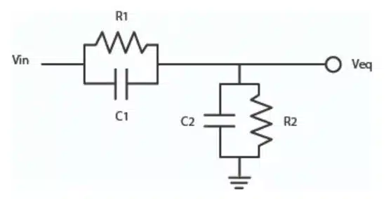
Figure 1. RC equalizer with a simple RC network. Source

Per the example, the transfer function is:

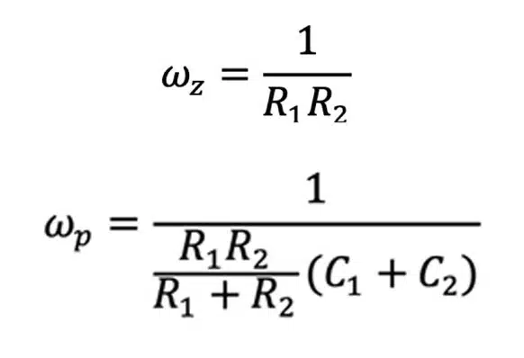
Zero frequency (top) and pole frequency (bottom) are:
Knowles Precision Devices’ DLI brand gain equalizers were designed to and maintain excellent, repeatable performance.

Related

Source: Knowles Precision Devices

Recent Posts

KYOCERA AVX Releases 600MHz Band71 Compact SAW Duplexer

30.7.2025
4

Switched Capacitor Converter Explained

28.7.2025
12

Researchers Demonstrated 200C Polymer Film Dielectric

28.7.2025
10

Researchers Demonstrated Zinc-Ion Based Photo-Supercapacitor

28.7.2025
9
Comparative display of a grain size and domain structure; b free energy; c P-E loops after high-entropy ceramics (HECs) and PGS design. source: Nature Communications  ISSN 2041-1723

Researchers Propose Novel MLCC Dielectric Design to Increase Energy Storage Capacity

24.7.2025
39

Understanding Inductor Dot Markings and Their Application in LTspice

21.7.2025
41

Murata Releases First High-Frequency XBAR Filter for Next-Gen Networks

8.7.2025
27

Würth Elektronik Present Efficient Motor Controller Evaluation Kit

8.7.2025
37

TDK Introduces High Current 80VDC Board-Mount EMI Filters

2.7.2025
39

Advancements and Applications of Switch Capacitor Power Converters

25.6.2025
45

Upcoming Events

Sep 22
September 22 @ 13:00 - September 25 @ 15:15 EDT

Pre Cap Visual Inspection per Mil-Std-883 (TM 2017)

Sep 30
September 30 @ 12:00 - October 2 @ 14:00 EDT

MIL-Std-883 TM 2010

Oct 17
12:00 - 14:00 EDT

External Visual Inspection per MIL-STD-883 TM 2009

Oct 21
October 21 @ 12:00 - October 23 @ 14:15 EDT

Space and Military Standards for Hybrids and RF Microwave Modules

Nov 4
November 4 @ 12:00 - November 6 @ 14:15 EST

Wirebond Materials, Processes, Reliability and Testing

View Calendar

Popular Posts

  • Buck Converter Design and Calculation

    0 shares
    Share 0 Tweet 0
  • Boost Converter Design and Calculation

    0 shares
    Share 0 Tweet 0
  • Flyback Converter Design and Calculation

    0 shares
    Share 0 Tweet 0
  • LLC Resonant Converter Design and Calculation

    0 shares
    Share 0 Tweet 0
  • What is a Dielectric Constant and DF of Plastic Materials?

    4 shares
    Share 4 Tweet 0
  • Dual Active Bridge (DAB) Topology Explained

    0 shares
    Share 0 Tweet 0
  • Ripple Current and its Effects on the Performance of Capacitors

    3 shares
    Share 3 Tweet 0
  • How to Design an Inductor

    0 shares
    Share 0 Tweet 0
  • MLCC Case Sizes Standards Explained

    0 shares
    Share 0 Tweet 0
  • MLCC and Ceramic Capacitors

    0 shares
    Share 0 Tweet 0

Newsletter Subscription


Passive Components Blog

© EPCI - Leading Passive Components Educational and Information Site

  • Home
  • Privacy Policy
  • EPCI Membership & Advertisement
  • About

No Result
View All Result
  • Home
  • Knowledge Blog
  • Premium Suppliers

© EPCI - Leading Passive Components Educational and Information Site

This website uses cookies. By continuing to use this website you are giving consent to cookies being used. Visit our Privacy and Cookie Policy.
Go to mobile version