Passive Components Blog
No Result
View All Result
  • Home
  • NewsFilter
    • All
    • Aerospace & Defence
    • Antenna
    • Applications
    • Automotive
    • Capacitors
    • Circuit Protection Devices
    • electro-mechanical news
    • Filters
    • Fuses
    • Inductors
    • Industrial
    • Integrated Passives
    • inter-connect news
    • Market & Supply Chain
    • Market Insights
    • Medical
    • Modelling and Simulation
    • New Materials & Supply
    • New Technologies
    • Non-linear Passives
    • Oscillators
    • Passive Sensors News
    • Resistors
    • RF & Microwave
    • Telecommunication
    • Weekly Digest

    3-Phase EMI Filter Design, Simulation, Calculation and Test

    YAGEO Unveils Compact 2.4 GHz SMD Antenna

    KYOCERA AVX Releases Antenna for Iridium Satellite IoT Applications

    Molex Releases Industry-First Quad-Row Board-to-Board Connectors with EMI Shields

    Image credit: Samtec

    How to Match the Right Connector with Protocol Requirements

    Smoltek CNF-MIM Capacitors Pass 1,000h Reliability Test

    Capacitor Lead Times: October 2025

    Paumanok Unveils Aluminum Capacitor Foils World Markets Study 2025-2030

    Coilcraft Introduces Ultra-Low Loss Shielded Power Inductors

    Trending Tags

    • Ripple Current
    • RF
    • Leakage Current
    • Tantalum vs Ceramic
    • Snubber
    • Low ESR
    • Feedthrough
    • Derating
    • Dielectric Constant
    • New Products
    • Market Reports
  • VideoFilter
    • All
    • Antenna videos
    • Capacitor videos
    • Circuit Protection Video
    • Filter videos
    • Fuse videos
    • Inductor videos
    • Inter-Connect Video
    • Non-linear passives videos
    • Oscillator videos
    • Passive sensors videos
    • Resistor videos

    3-Phase EMI Filter Design, Simulation, Calculation and Test

    Transformer Design Optimization for Power Electronics Applications

    Common Mode Chokes Selection for RF Circuits in Next-Generation Communication Systems

    Capacitor Self-balancing in a Flying-Capacitor Buck Converter

    How to Select Ferrite Bead for Filtering in Buck Boost Converter

    Power Inductors Future: Minimal Losses and Compact Designs

    Percolation Phenomenon: Degradation of Molded Power Inductors in DC/DC Converters

    Connector PCB Design Challenges

    Efficient Power Converters: Duty Cycle vs Conduction Losses

    Trending Tags

    • Capacitors explained
    • Inductors explained
    • Resistors explained
    • Filters explained
    • Application Video Guidelines
    • EMC
    • New Products
    • Ripple Current
    • Simulation
    • Tantalum vs Ceramic
  • Knowledge Blog
  • Suppliers
    • Who is Who
  • PCNS
    • PCNS 2025
    • PCNS 2023
    • PCNS 2021
    • PCNS 2019
    • PCNS 2017
  • Events
No Result
View All Result
Passive Components Blog
No Result
View All Result

Passive Gain Equalizer Explained

15.11.2023
Reading Time: 3 mins read
A A

This article based on Knowles Precision Devices blog explains basic about passive gain equalizer and how they are working.

Passive gain equalizers are designed to rectify or flatten the frequency response of an RF amplifier. RF amplifiers are known to cause a non-uniform gain over the operational bandwidth of a device, which results in distortion and other unwanted effects. Equalizers generate a counter-gain profile to offset that uneven response.

RelatedPosts

Knowles Releases High Q Non-Magnetic X7R MLCCs for Medical Imaging

Knowles Unveils High-Performance Safety-Certified MLCC Capacitors

Knowles Releases Inductors for Mission-Critical RF Applications

Pairing equalizers and amplifiers is critical in applications like broadband systems where consistent performance over a wide frequency range enhances signal fidelity and system performance.

Passive gain equalizers offer a variety of ancillary benefits too:

  • Enhanced durability and reliability by design; passive gain equalizers lack active components, which wear faster over time.
  • Flexibility for system designers; with a wide variety of shapes, sizes, and equalizing profiles to work with, it’s easier to match gain variation profiles.
  • No external power supply needed; these components are ideal for situations where power is limited or introducing power would cause interference.
  • Low noise; as passive devices, equalizers aren’t known to be noisy, so they’re well-suited for high-frequency applications where signal integrity is an important parameter.

Resistor-Capacitor (RC) Gain Equalizers RF and Microwave Systems

Over long distances, signal gain is more frequency-dependent, which causes some components of a signal to be amplified more or less than others. RC gain equalizers offset the impact of signal distortion that’s caused by long-distance signal transmission. As their name implies, these circuits use a network of resistors and capacitors to create a frequency response that applies an equal and opposite amount of gain to a signal.

In practice, when a signal passes through an equalizer, it encounters different levels of resistance and reactance. Lower-frequency signals mostly pass through the resistors because the capacitors appear to create an open circuit. Alternatively, higher-frequency signals pass through the capacitors because the resistors appear to create a short circuit. Capacitor and resistor selection play an important role in counteracting that unequal gain.

The structure of an RC gain equalizer depends on application requirements. In this example, from optical networking, frequency shaping is achieved using a simple RC network for gain and suppression at the right frequency, which depends on the resistor (R) and capacitor (C) values in the series and parallel networks. 

Figure 1. RC equalizer with a simple RC network. Source

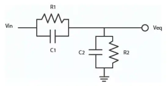
Per the example, the transfer function is:

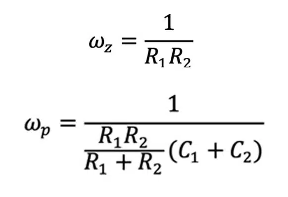
Zero frequency (top) and pole frequency (bottom) are:

Knowles Precision Devices’ DLI brand gain equalizers were designed to and maintain excellent, repeatable performance.

Related

Source: Knowles Precision Devices

Recent Posts

3-Phase EMI Filter Design, Simulation, Calculation and Test

6.11.2025
8
Image credit: Samtec

How to Match the Right Connector with Protocol Requirements

6.11.2025
3

Transformer Design Optimization for Power Electronics Applications

4.11.2025
11

Microhardness — the Hidden Key to Understanding MnOx Cathode Quality in Tantalum Capacitors

3.11.2025
20

Lightweight Model for MLCC Appearance Defect Detection

3.11.2025
22

Common Mode Chokes Selection for RF Circuits in Next-Generation Communication Systems

30.10.2025
16

Capacitor Self-balancing in a Flying-Capacitor Buck Converter

30.10.2025
40

How to Select Ferrite Bead for Filtering in Buck Boost Converter

23.10.2025
53

Power Inductors Future: Minimal Losses and Compact Designs

30.10.2025
59

Percolation Phenomenon: Degradation of Molded Power Inductors in DC/DC Converters

30.10.2025
61

Upcoming Events

Nov 11
17:00 - 18:00 CET

Industrial Applications Demand More from Interconnects in Next-Gen Designs

Nov 12
11:00 - 12:00 CET

PCB Design: Impedance is for everyone!

Nov 12
November 12 @ 12:00 - November 13 @ 14:15 EST

Microelectronic Packaging Failure Modes and Analysis

View Calendar

Popular Posts

  • Buck Converter Design and Calculation

    0 shares
    Share 0 Tweet 0
  • Boost Converter Design and Calculation

    0 shares
    Share 0 Tweet 0
  • LLC Resonant Converter Design and Calculation

    0 shares
    Share 0 Tweet 0
  • Flyback Converter Design and Calculation

    0 shares
    Share 0 Tweet 0
  • Ripple Current and its Effects on the Performance of Capacitors

    3 shares
    Share 3 Tweet 0
  • MLCC and Ceramic Capacitors

    0 shares
    Share 0 Tweet 0
  • Dual Active Bridge (DAB) Topology

    0 shares
    Share 0 Tweet 0
  • What is a Dielectric Constant and DF of Plastic Materials?

    4 shares
    Share 4 Tweet 0
  • SEPIC Converter Design and Calculation

    0 shares
    Share 0 Tweet 0
  • Flying Capacitors

    0 shares
    Share 0 Tweet 0

Newsletter Subscription


Passive Components Blog

© EPCI - Leading Passive Components Educational and Information Site

  • Home
  • Privacy Policy
  • EPCI Membership & Advertisement
  • About

No Result
View All Result
  • Home
  • Knowledge Blog
  • PCNS

© EPCI - Leading Passive Components Educational and Information Site

This website uses cookies. By continuing to use this website you are giving consent to cookies being used. Visit our Privacy and Cookie Policy.
Go to mobile version