Passive Components Blog
No Result
View All Result
  • Home
  • NewsFilter
    • All
    • Aerospace & Defence
    • Antenna
    • Applications
    • Automotive
    • Capacitors
    • Circuit Protection Devices
    • electro-mechanical news
    • Filters
    • Fuses
    • Inductors
    • Industrial
    • Integrated Passives
    • inter-connect news
    • Market & Supply Chain
    • Market Insights
    • Medical
    • Modelling and Simulation
    • New Materials & Supply
    • New Technologies
    • Non-linear Passives
    • Oscillators
    • Passive Sensors News
    • Resistors
    • RF & Microwave
    • Telecommunication
    • Weekly Digest

    Smolteks CNF MIM Capacitor Break 1 µF/mm²

    Samsung Electro-Mechanics Releases 0201 X7T 1uF 6.3V MLCC for ADAS Applications

    Murata Announces 0402 Automotive Chip Ferrite Beads for V2X

    2025 Thick and Thin Film Resistor Networks Environment Overview

    Role of High-Q Ceramic Filters to Overcome GNSS Jamming

    Optimization of IoT for GEO NB-NTN Hybrid Connectivity

    TDK Releases Automotive Power-Over-Coax Inductor for Filters

    Advanced Conversion Announces Mass Production of 200C Film Capacitors

    VinaTech Supercapacitors: Enhancing Smart Meter Reliability and Efficiency

    Trending Tags

    • Ripple Current
    • RF
    • Leakage Current
    • Tantalum vs Ceramic
    • Snubber
    • Low ESR
    • Feedthrough
    • Derating
    • Dielectric Constant
    • New Products
    • Market Reports
  • VideoFilter
    • All
    • Antenna videos
    • Capacitor videos
    • Circuit Protection Video
    • Filter videos
    • Fuse videos
    • Inductor videos
    • Inter-Connect Video
    • Non-linear passives videos
    • Oscillator videos
    • Passive sensors videos
    • Resistor videos

    Understanding Switched Capacitor Converters

    Coupled Inductors Circuit Model and Examples of its Applications

    Inductor Resonances and its Impact to EMI

    Highly Reliable Flex Rigid PCBs, Würth Elektronik Webinar

    Causes of Oscillations in Flyback Converters

    How to design a 60W Flyback Transformer

    Modeling and Simulation of Leakage Inductance

    Power Inductor Considerations for AI High Power Computing – Vishay Video

    Coupled Inductors in Multiphase Boost Converters

    Trending Tags

    • Capacitors explained
    • Inductors explained
    • Resistors explained
    • Filters explained
    • Application Video Guidelines
    • EMC
    • New Products
    • Ripple Current
    • Simulation
    • Tantalum vs Ceramic
  • Knowledge Blog
  • Suppliers
    • Who is Who
  • Events
No Result
View All Result
Passive Components Blog
No Result
View All Result

Replacing Aluminum Electrolytic Capacitors with Tantalum or Ceramic Capacitors

7.6.2022
Reading Time: 6 mins read
A A

This article written by Teddy Won, KYOCERA-AVX Components Corporation, discusses shortcomings and replacing of aluminum electrolytic capacitors with tantalum capacitors or ceramic MLCC capacitors.

Introduction to Electrolytic Capacitors

Like all capacitors, electrolytic capacitors (shortly electrolytics or e-caps) are based on the principle of storing energy in an electric field using a voltage applied across a dielectric.

RelatedPosts

Optimization of IoT for GEO NB-NTN Hybrid Connectivity

KYOCERA AVX Presents Chip Antennas for SiP Market

Capacitor Ripple Current Testing: A Design Consideration

The basic structure of this arrangement is shown in figure 1, where two metallic plates are used to contact the dielectric.

Electrolytic capacitors are unique in that the dielectric is formed by growing an oxide on the surface of a metallic (typically aluminum or tantalum) foil.

This oxide acts as a unidirectional insulator and gives the electrolytic capacitor its polarized characteristic. An electrolyte (typically liquid) is employed to interface with the irregular and rough oxide surface to make electrical contact with the other side of the oxide layer.

Figure 1 – Basic capacitor structure

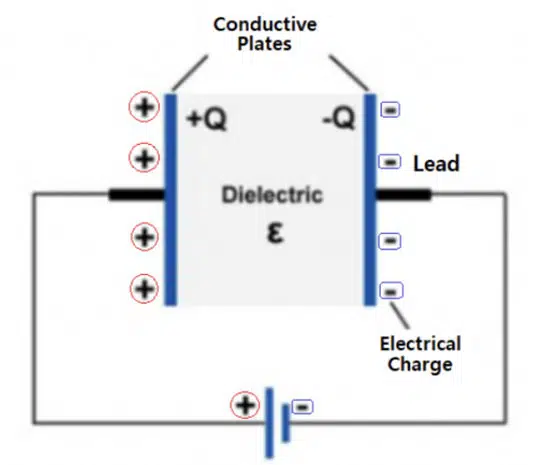
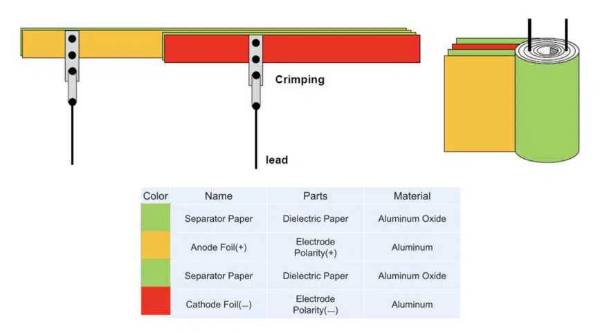
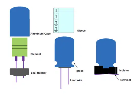
Figure 2 shows that the foil-oxide-electrolyte foil structure is crimped into two wire leads and rolled to form the internal capacitor structure. It is worth noting that the electrolyte is often impregnated within a paper substrate for manufacturing purposes.

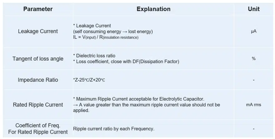
The impedance ratio describes the linearized temperature sensitivity of the impedance. Aluminum electrolytic capacitors often exhibit poor temperature sensitivity making them difficult to design into harsh environments. The rated ripple current is a limiting value that restricts an output ripple current below a certain level to prevent damage from self-heating.

Figure 2 – Aluminum electrolytic capacitor core

This is intimately coupled to ESR since the internal resistance is the source of self-heating. Finally, the frequency coefficient for rated ripple details the acceptable ripple currents across different frequency ranges. In switching converter applications, knowledge of the frequency dependence is critical for selecting output capacitors. Table 1. provides overview of the most common capacitor electrical parameters such as DCL Leakage Current, DF Dissipation Factor (= tangent of loss angle tgd), Impedance and Ripple Current.

Figure 3 – Electrolytic capacitor case
Table 1 – Common electrolytic capacitor parameters

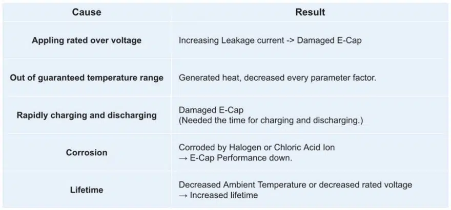
The Shortcomings of Aluminum Electrolytic Capacitors

Just like any other capacitor technology, aluminum electrolytics exhibit sensitivities that are undesirable in certain applications and must be accounted for during component selection. While their voltage ratings can be extremely high, they are generally sensitive to heat. In addition, due to a relatively high internal resistance, aluminum electrolytics require charge and discharge rates to be controlled concerning self-heating.

Finally, aluminum electrolytics can be sensitive to corrosion and have a relatively limited lifetime compared to other capacitor structures. These qualities are summarized in table 2. In high-reliability applications, such as automotive, Aluminum electrolytics can pose additional challenges. Their physical structure makes them sensitive to vibration induced failure modes. Special lead and case designs must be employed in these environments.

In addition, commonly used liquid electrolytes can introduce additional failure modes when external temperatures induce vaporization. When combined with the large physical size of aluminum electrolytics, and their relatively high variation specifications, they generally become unattractive for high-reliability applications.

Table 2 – Aluminum electrolytic capacitors failure modes

Replacing Aluminum Electrolytic Capacitors

Figure 4 – Output capacitor choice in a DC/DC converter design

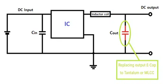
Designs are often required to meet certain regulatory standards that specify performance around reliability, environment, and performance. These must be reconciled with traditional concerns of size and cost. As a simple example, consider the output smoothing capacitor shown in the DC/DC converter design in figure 4.

The configuration of the output capacitor in figure 4 has a fixed and known polarity. That allows aluminum electrolytics, tantalum or multilayer MLCCs to be possible candidates for use. If the application demands long life, extreme temperature tolerance, or small physical size, then traditional aluminum electrolytics may not be optimal. As shown in figure 5, if a large bulk capacitance and low voltage are required, then the tantalum option may be preferable. If the voltage is particularly high or ripple performance is critical, then several low ESR MLCCs in parallel may be suitable.

Figure 5 – Comparison of voltage rating and lifetime for MLCCs and electrolytics

Conclusion

Given cost requirements and any other specific performance demands, there exist a wide variety of capacitor options that could readily replace the aluminum electrolytic capacitor.

Table 3 presents a high-level comparison between MLCC, aluminum electrolytic, and tantalum capacitors. Whenever lifetime reliability, temperature stability, or size are of paramount importance, one should consider replacing aluminum electrolytic capacitors in a design with MLCC’s or tantalum devices. Multiple MLCC’s may be necessary to achieve the required capacitance, and the bill of material costs might require adjustments for tantalum devices, but the resulting performance will justify the change.

Table 3 – An overall comparison of ceramic, aluminum electrolytic, and tantalum capacitors

Related

Source: KYOCERA AVX

Recent Posts

Smolteks CNF MIM Capacitor Break 1 µF/mm²

19.6.2025
20

Samsung Electro-Mechanics Releases 0201 X7T 1uF 6.3V MLCC for ADAS Applications

19.6.2025
8

Murata Announces 0402 Automotive Chip Ferrite Beads for V2X

19.6.2025
19

Optimization of IoT for GEO NB-NTN Hybrid Connectivity

19.6.2025
5

Advanced Conversion Announces Mass Production of 200C Film Capacitors

18.6.2025
18

VinaTech Supercapacitors: Enhancing Smart Meter Reliability and Efficiency

17.6.2025
15

KYOCERA AVX Presents Chip Antennas for SiP Market

16.6.2025
11

Chinas MLCC Makers Reach 10% Market Share

16.6.2025
63

Würth Elektronik Releases Long Life SMT nano and microSD Card Connectors

12.6.2025
9

Murata Releases Worlds First Molded Thermistor with Wire-Bonding

12.6.2025
19

Upcoming Events

Jun 24
16:00 - 17:00 CEST

Limitations of PSFB converters and improvements by a variable inductor ft. Sam Ben-Yaakov

Jun 24
17:00 - 18:00 CEST

Ultra-Compact and Efficient Switched-Capacitor Power Converters

Jul 23
13:00 - 14:00 CEST

PCB design for a Smartwatch

View Calendar

Popular Posts

  • Buck Converter Design and Calculation

    0 shares
    Share 0 Tweet 0
  • Boost Converter Design and Calculation

    0 shares
    Share 0 Tweet 0
  • Flyback Converter Design and Calculation

    0 shares
    Share 0 Tweet 0
  • What is a Dielectric Constant and DF of Plastic Materials?

    4 shares
    Share 4 Tweet 0
  • LLC Resonant Converter Design and Calculation

    0 shares
    Share 0 Tweet 0
  • Ripple Current and its Effects on the Performance of Capacitors

    3 shares
    Share 3 Tweet 0
  • How to Design an Inductor

    0 shares
    Share 0 Tweet 0
  • SEPIC Converter Design and Calculation

    0 shares
    Share 0 Tweet 0
  • Dual Active Bridge (DAB) Topology Explained

    0 shares
    Share 0 Tweet 0
  • Why Low ESR Matters in Capacitor Design

    0 shares
    Share 0 Tweet 0

Newsletter Subscription


Passive Components Blog

© EPCI - Leading Passive Components Educational and Information Site

  • Home
  • Privacy Policy
  • EPCI Membership & Advertisement
  • About

No Result
View All Result
  • Home
  • Knowledge Blog
  • Premium Suppliers

© EPCI - Leading Passive Components Educational and Information Site

This website uses cookies. By continuing to use this website you are giving consent to cookies being used. Visit our Privacy and Cookie Policy.
Go to mobile version