Passive Components Blog
No Result
View All Result
  • Home
  • NewsFilter
    • All
    • Aerospace & Defence
    • Antenna
    • Applications
    • Automotive
    • Capacitors
    • Circuit Protection Devices
    • electro-mechanical news
    • Filters
    • Fuses
    • Inductors
    • Industrial
    • Integrated Passives
    • inter-connect news
    • Market & Supply Chain
    • Market Insights
    • Medical
    • Modelling and Simulation
    • New Materials & Supply
    • New Technologies
    • Non-linear Passives
    • Oscillators
    • Passive Sensors News
    • Resistors
    • RF & Microwave
    • Telecommunication
    • Weekly Digest

    YAGEO Introduces C0G Flexible Termination Automotive MLCCs

    SCHURTER Releases SMT Micro Switch for Compact HMIs

    binder Releases Tool‑Tightenable M12 Connectors for Improved Reliability

    Vishay Introduced Thin Film Submount Platform for Optical and RF Modules

    Murata Introduces Crystal and NTC Set for Automotive UWB Timing

    Kyocera Developed Multilayer Ceramic Core Substrate for AI Packages

    Modeling Fringing Field Losses in Inductors & Transformers

    YMIN Introduces Polymer Tantalum Capacitors for AI Server SSDs

    Littelfuse Expands High-Voltage TVS Diodes

    Trending Tags

    • Ripple Current
    • RF
    • Leakage Current
    • Tantalum vs Ceramic
    • Snubber
    • Low ESR
    • Feedthrough
    • Derating
    • Dielectric Constant
    • New Products
    • Market Reports
  • VideoFilter
    • All
    • Antenna videos
    • Capacitor videos
    • Circuit Protection Video
    • Filter videos
    • Fuse videos
    • Inductor videos
    • Inter-Connect Video
    • Non-linear passives videos
    • Oscillator videos
    • Passive sensors videos
    • Resistor videos

    Modeling Fringing Field Losses in Inductors & Transformers

    Why Power Inductors Use a Ferrite Core With an Air Gap

    Transformer-Based Power-Line Harvester Magnetic Design

    Thermal Modeling of Magnetics

    Standard vs Planar LLC transformers Comparison for Battery Chargers

    How Modern Tools Model Magnetic Components for Power Electronics

    Advanced Loss Modeling for Planar Magnetics in the Frenetic Planar Tool

    2026 Power Magnetics Design Trends: Flyback, DAB and Planar

    Enabling Software‑Defined Vehicle Architectures: Automotive Ethernet and Zonal Smart Power

    Trending Tags

    • Capacitors explained
    • Inductors explained
    • Resistors explained
    • Filters explained
    • Application Video Guidelines
    • EMC
    • New Products
    • Ripple Current
    • Simulation
    • Tantalum vs Ceramic
  • Knowledge Blog
  • DossiersNew
  • Suppliers
    • Who is Who
  • PCNS
    • PCNS 2025
    • PCNS 2023
    • PCNS 2021
    • PCNS 2019
    • PCNS 2017
  • Events
No Result
View All Result
Passive Components Blog
No Result
View All Result

SCHURTER Releases SMT Micro Switch for Compact HMIs

30.4.2026
Reading Time: 6 mins read
A A

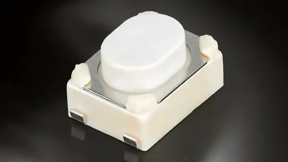
The SCHURTER TCS43 is a microminiature surface mount tactile (micro) switch aimed at space‑constrained human–machine interfaces that still require clear, reliable haptic feedback.

It combines a tiny footprint with selectable actuation forces and a robust operating range, making it relevant for next‑generation consumer, IoT, and medical devices.

RelatedPosts

SCHURTER Releases Compact SMT DIP Switches

SCHURTER Introduces 2410 SMD Fuse for Robust AC/DC Protection

Schurter Releases EKO HV Fuses up to 1000 VDC, 1100 A

Key features and benefits

  • Microminiature SMT footprint: 4.2 × 3.2 mm outline and approx. 2.5 mm height support very dense PCB layouts in handheld and portable equipment.
  • Surface‑mount assembly: Designed for SMT reflow processes, simplifying automated assembly and reducing the need for manual post‑assembly operations compared with through‑hole tact switches.
  • Selectable actuation forces: Three variants with 180 gf, 250 gf, and 400 gf (approximately 1.76 N to 3.92 N) give designers control over the “click feel” and required finger force for different user groups and applications.
  • Defined tactile feedback: Short travel with clear actuation point supports precise, repeatable user interaction, important for menu navigation and safety‑relevant functions.
  • Mechanical endurance: Up to 100,000 actuation cycles according to manufacturer datasheet, suitable for low‑to‑moderate switch utilization in medical and consumer HMI points.
  • Low‑power electrical ratings: 10 µA to 50 mA current and 1 to 12 VDC voltage range allow direct use in low‑voltage logic and microcontroller interfaces without additional high‑power switching elements.
  • Stable contact resistance: Contact resistance specified as ≤100 mΩ helps maintain signal integrity and predictable voltage levels in digital input circuits.
  • Wide operating temperature range: Rated operation from −40 °C to +90 °C supports use in indoor, light industrial, and many medical environments where extended temperature capability is needed.

Typical applications

The Schurter TCS43 is targeted at user interface and control functions where PCB space is limited and a distinct mechanical feedback is required.

  • On/off and standby keys in high‑end consumer electronics such as audio systems, smart speakers, and remote controls.
  • Menu navigation and parameter selection keys on front panels of measurement instruments and compact lab devices.
  • Human–machine interface inputs in home automation and building control panels, including wall‑mounted scene controllers and thermostats.
  • User input buttons in IoT devices, gateways, and compact wireless nodes where battery operation and low‑power design are critical.
  • Medical equipment control keys, such as those found on blood pressure monitors, ventilators, and other patient interface devices, where consistent tactile response supports safe operation.

In many of these use cases, the small outline and low profile of the switch allow it to be placed directly under thin plastic keycaps, membrane overlays, or silicone rubber keymats while keeping the overall device height under control.

Technical highlights

The table below summarizes the key electrical and mechanical parameters as specified by SCHURTER for the TCS43 series.

ParameterTCS43 specification (according to SCHURTER)
Mounting styleSurface mount (SMT)
Footprint4.2 × 3.2 mm
Heightapprox. 2.5 mm
Actuation force options180 gf, 250 gf, 400 gf
Actuation force (approx. N)1.76 N, 2.45 N, 3.92 N
Mechanical lifetimeup to 100,000 cycles
Voltage rating1 to 12 VDC
Current rating10 µA to 50 mA
Contact resistance≤100 mΩ
Operating temperature range−40 °C to +90 °C

From a circuit perspective, the low current and voltage ratings reflect a signal‑level switch intended for logic and control inputs, not for directly switching mains or high‑power loads. The specified contact resistance ceiling is typical for tactile switches in this size class and is generally compatible with standard pull‑up or pull‑down resistor values in the tens of kiloohms.

Haptic behavior and user feel

  • The 180 gf variant suits applications where a lighter touch is desired, for example compact handheld instruments or devices for users with reduced finger strength.
  • The 250 gf mid‑range option offers a balance between effort and feedback, suitable for general consumer and IoT interfaces.
  • The 400 gf version demands a clearly intentional press, reducing the risk of accidental operation for critical keys such as power or mode selection.

In all cases, the combination of defined force and clear tactile response helps users recognize that a function has been triggered without needing to look at the device, which is particularly valuable in medical and professional environments.

Design‑in notes for engineers

This section focuses on practical design‑in aspects when integrating the TCS43 into new or existing PCB designs.

  • Define required tactile force early: Determine which of the 180 gf, 250 gf, or 400 gf options best matches the product’s user profile, safety needs, and ergonomic goals before finalizing front‑panel mechanics.
  • Observe electrical limits: Ensure that the switch only carries currents and voltages within the 10 µA to 50 mA and 1 to 12 VDC range; higher loads should be switched via appropriate transistors or relays.
  • Use clean signal conditioning: Combine the switch with suitable pull‑up or pull‑down resistors and, where necessary, RC debouncing or firmware debouncing to guarantee stable logic transitions.
  • Design the land pattern per datasheet: Follow the recommended PCB pad layout and solder mask openings from the manufacturer to achieve reliable solder joints and minimize tilt or coplanarity issues.
  • Consider overlay and actuator design: Align the TCS43 properly with keycaps, domes, or membrane bumps so that the actuation force is applied centrally and perpendicular to the switch plunger.
  • Check stack‑up height: Account for the 2.5 mm switch height plus overlay thickness to ensure the complete HMI stack meets the target enclosure height and mechanical tolerances.
  • Thermal considerations in reflow: Verify that the reflow profile used on the production line is compatible with the switch’s thermal limits specified in the datasheet to avoid mechanical damage or performance drift.
  • Environmental robustness: For applications at the extremes of the −40 °C to +90 °C range, verify long‑term performance through testing and confirm any additional sealing or protection measures required at system level.
  • Serviceability and life: With a mechanical life up to 100,000 cycles, match the switch selection to the expected number of actuations in the final application and consider maintenance or replacement strategy if necessary.

For engineers migrating from larger tact switches, the TCS43’s small footprint can free up board area for additional functionality, but it also demands tighter mechanical tolerances on housing and overlay parts to maintain consistent user feel.

Source

The information in this article is based on the SCHURTER TCS43 SMT micro switch news release and the associated manufacturer documentation and datasheet, adapted and commented for design engineers and component purchasers.

References

  1. SCHURTER news: TCS43 – SMT Micro Switch
  2. SCHURTER TCS43 datasheet

Related

Recent Posts

YAGEO Introduces C0G Flexible Termination Automotive MLCCs

30.4.2026
0

binder Releases Tool‑Tightenable M12 Connectors for Improved Reliability

30.4.2026
2

Vishay Introduced Thin Film Submount Platform for Optical and RF Modules

30.4.2026
4

Exxelia Introduces SMD High‑Voltage Mica Capacitors

28.4.2026
19

April 2026 Interconnect, Passives and Electromechanical Components Market Insights

22.4.2026
76

KYOCERA AVX Introduces Traction‑Grade DC Link Film Capacitors

21.4.2026
48

YAGEO Introduces High‑Current Y2/X1 Film Capacitors for Wide-bandgap Power Systems

17.4.2026
43

Amphenol Explanded Liquid Cooling Connectors for AI, ESS and EV Systems

17.4.2026
24

Hirose Introduced BGA connector for PCIe Gen6 for AI and Edge Computing

17.4.2026
14

Upcoming Events

May 5
16:00 - 17:00 CEST

Understanding and Selecting Capacitors – Fundamentals, Technologies and Latest Trends

May 7
17:00 - 18:00 CEST

From Grid to Motion: How Industrial Electrification is Redefining Power System Design

May 12
8:00 - 15:00 CEST

ESCC Space Splice connectors

View Calendar

Popular Posts

  • Buck Converter Design and Calculation

    0 shares
    Share 0 Tweet 0
  • Boost Converter Design and Calculation

    0 shares
    Share 0 Tweet 0
  • Flyback Converter Design and Calculation

    0 shares
    Share 0 Tweet 0
  • LLC Resonant Converter Design and Calculation

    0 shares
    Share 0 Tweet 0
  • MLCC and Ceramic Capacitors

    0 shares
    Share 0 Tweet 0
  • Dual Active Bridge (DAB) Topology

    0 shares
    Share 0 Tweet 0
  • What Electronics Engineer Needs to Know About Passive Low Pass Filters

    0 shares
    Share 0 Tweet 0
  • Capacitor Charging and Discharging

    0 shares
    Share 0 Tweet 0
  • MLCC Case Sizes Standards Explained

    0 shares
    Share 0 Tweet 0
  • Ripple Current and its Effects on the Performance of Capacitors

    3 shares
    Share 3 Tweet 0

Newsletter Subscription


Passive Components Blog

© EPCI - Leading Passive Components Educational and Information Site

  • Home
  • Privacy Policy
  • EPCI Membership & Advertisement
  • About

No Result
View All Result
  • Home
  • Knowledge Blog
  • PCNS

© EPCI - Leading Passive Components Educational and Information Site

This website uses cookies. By continuing to use this website you are giving consent to cookies being used. Visit our Privacy and Cookie Policy.
Go to mobile version