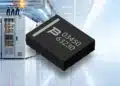









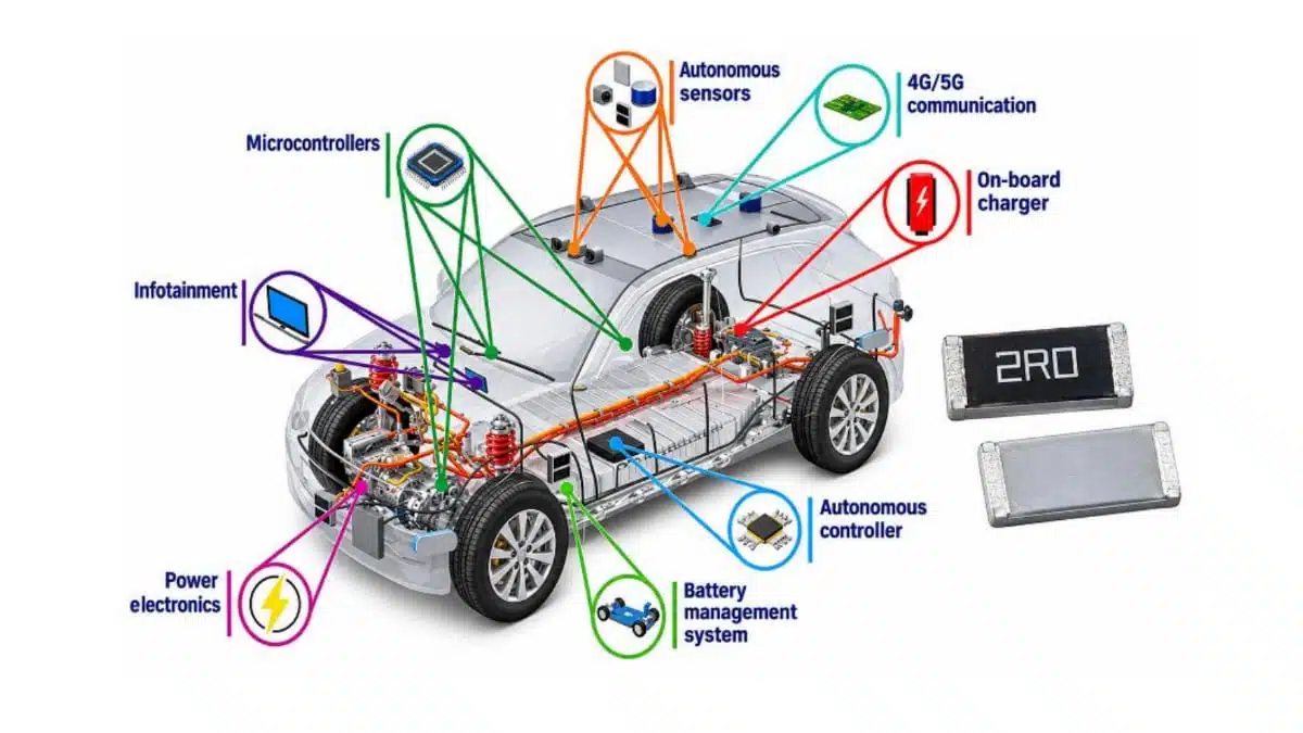
Stackpole’s RPCQ series comprises automotive-grade, pulse-withstanding thick-film chip resistors in 1206 and 2512 case sizes.
Power ratings of 1 W and 4 W at 70 °C combine with AEC-Q200 qualification and anti-sulfur testing for automotive electronics, industrial power supplies and motor controls.
Key features and benefits
- Two case sizes: RPCQ1206 rated at 1 W and RPCQ2512 rated at 4 W, both at 70 °C.
- Resistance range of 1 Ω to 1 MΩ, with tolerance options of ±2%, ±5% and ±10%.
- Maximum working-voltage ceilings of 200 V for RPCQ1206 and 250 V for RPCQ2512.
- Operating temperature range of −55 °C to +175 °C.
- Anti-sulfur performance tested to ASTM-B-809-95 and ANSI/EIA 977.
- Separate single-pulse power, continuous-pulse power and pulse-voltage characteristics for pulse-load selection.
Technical highlights
Electrical ratings and package dimensions
The RPCQ2512 combines a higher continuous power rating with a larger body than the RPCQ1206. Package selection therefore involves both the electrical load and the PCB area allocated to the resistor.
| Parameter | RPCQ1206 | RPCQ2512 |
|---|---|---|
| Case size | 1206 | 2512 |
| Rated power at 70 °C | 1 W | 4 W |
| Maximum working voltage | 200 V | 250 V |
| Maximum overload voltage | 400 V | 500 V |
| Resistance range | 1 Ω–1 MΩ | 1 Ω–1 MΩ |
| Resistance tolerance | ±2%, ±5%, ±10% | ±2%, ±5%, ±10% |
| Operating temperature | −55 °C to +175 °C | −55 °C to +175 °C |
| Body length | 3.05 ± 0.10 mm | 6.30 ± 0.20 mm |
| Body width | 1.60 ± 0.10 mm | 3.20 ± 0.15 mm |
| Body height | 0.65 ± 0.15 mm | 0.75 ± 0.15 mm |
The maximum working voltage is a ceiling, not the permitted continuous voltage for every resistance value. The allowable working voltage is the lower of the resistance-dependent power limit and the package’s maximum working voltage. Overload selection likewise combines a resistance-dependent limit with the maximum overload voltage.
This distinction matters across the resistance range: a resistor can reach its power limit before reaching the package voltage ceiling. Continuous power, operating voltage and transient loading must therefore be assessed together.
Pulse loading and environmental performance
RPCQ pulse-withstanding resistors have separate characteristics for single and repetitive pulse loading. A continuous wattage rating does not replace the pulse-duration and repetition assessment.
The single-pulse high-voltage overload test uses a 10/700 µs waveform, with ten pulses applied at one pulse per minute. Its resistance-change limit is ±(1% + 0.05 Ω). That test condition is distinct from continuous operation and from repetitive pulse-power capability.
The series also combines AEC-Q200 qualification with sulfur-resistant resistor performance. Environmental test conditions and resistance-change limits include:
| Test | Conditions | Resistance-change limit |
|---|---|---|
| Sulfur exposure | 105 ± 2 °C; 1,000 h; unpowered | ±(2% + 0.05 Ω) |
| Biased humidity | 85 °C; 85% RH; 1,000 h; 10% operating power | ±(3% + 0.05 Ω) |
| High-temperature storage | 175 °C; 1,000 h; unpowered | ±(3% + 0.05 Ω) |
These limits combine a percentage term with an absolute resistance term. Both terms matter when setting the permitted resistance drift, particularly toward the lower end of the resistance range.
Typical applications
Target applications include automotive electronics, data servers, industrial controls, switching power-supply regulation and motor controls. Power-electronics switching and electric-motor operation can expose resistors to inrush and pulse loads, making pulse duration and repetition relevant alongside continuous dissipation.
The 1 W RPCQ1206 and 4 W RPCQ2512 provide different starting points for continuous-load selection. Their respective 200 V and 250 V working-voltage ceilings also affect selection in higher-voltage circuit positions, subject to the resistance-dependent power limit.
For industrial equipment exposed to sulfur contamination, the sulfur test adds an environmental selection criterion alongside electrical loading. In automotive electronics, AEC-Q200 qualification forms part of component selection; circuit-level pulse and thermal requirements still govern the individual resistor choice.
Design-in notes for engineers
- Assess continuous dissipation and local operating temperature together. The 1 W and 4 W ratings apply at 70 °C; use the power-derating characteristic when establishing the operating load.
- Compare the actual pulse waveform, duration and repetition with the corresponding single-pulse, continuous-pulse and pulse-voltage characteristics.
- Apply both the resistance-dependent voltage limit and the package voltage ceiling. Treat overload voltage separately from continuous working voltage.
- Include initial tolerance, temperature-dependent resistance change and the applicable environmental drift allowance in the circuit error budget.
- Use the package-specific recommended solder pads and reflow profile when preparing the PCB footprint and assembly process.
- Validate the final selection under the actual electrical, thermal and environmental operating conditions before production release.
Pricing depends on package size and tolerance. Specific and volume quotations are available from Stackpole and its franchised distribution partners.
Further reading
- Stackpole Releases 2-Watt Pulse Withstanding Chip Resistor
- Passive Components J-STD-075 Process Sensitivity Explained
Source
This article is based on the Stackpole Electronics product announcement and official product documentation. Engineers should refer to the current manufacturer datasheet for final design and qualification.
References
- RPCQ Series: Automotive Grade High Power Pulse Withstanding Chip Resistor, Stackpole Electronics, June 27, 2025.
- Stackpole Releases New RPCQ Automotive Grade High Power Pulse Withstanding Chip Resistors, Stackpole Electronics, March 4, 2025.
- Stackpole’s RPCQ Pulse Withstanding Resistors Improve Reliability in Demanding Automotive and Industrial Applications, Stackpole Electronics, November 9, 2026.