











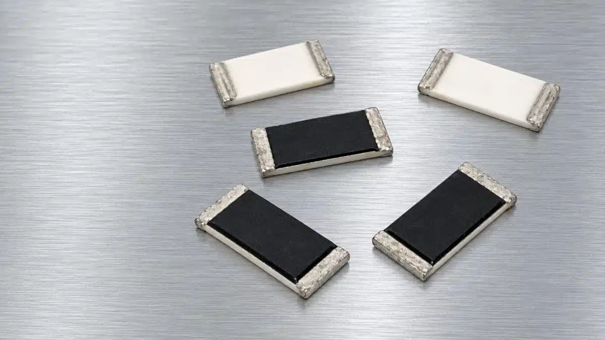
Stackpole Electronics has introduced the RMAN series of thick-film chip resistors on aluminum nitride (AlN) substrates for industrial and automotive power electronics.
The thick film chip resistors family combines surface-mount construction with power ratings of 2.4 W in 1206 and 3.5 W in 2512 at 70 °C, making substrate choice and thermal design central to component selection.
Key features and benefits
- AlN substrate: Thick-film resistive technology on aluminum nitride provides the construction basis for the series.
- Two package options: RMAN1206 and RMAN2512 cover different resistance and power requirements.
- Resistance ranges: 10 Ω to 2 kΩ for RMAN1206 and 3 Ω to 2 kΩ for RMAN2512.
- Tolerance options: ±1% and ±5%, with a temperature coefficient of resistance of ±150 ppm/°C.
- Operating temperature: −55 °C to +155 °C.
- Material compliance: RoHS compliant, REACH compliant and halogen free.
Technical highlights
Electrical selection
| Parameter | RMAN1206 | RMAN2512 |
|---|---|---|
| Case size | 1206 | 2512 |
| Rated power at 70 °C | 2.4 W | 3.5 W |
| Resistance range | 10 Ω–2 kΩ | 3 Ω–2 kΩ |
| Resistance tolerance | ±1%, ±5% | ±1%, ±5% |
| TCR | ±150 ppm/°C | ±150 ppm/°C |
| Operating temperature | −55 °C to +155 °C | −55 °C to +155 °C |
The maximum working voltage follows the resistance-dependent relationship , where P is rated power and R is resistance. Voltage selection therefore depends on the chosen resistance and package, rather than a single working-voltage value across the family.
Initial resistance tolerance and TCR govern different parts of the error budget. The tolerance controls the starting resistance spread; TCR governs resistance variation with temperature. Both need to match the circuit’s allowable resistance variation.
Dimensions and assembly
| Parameter | RMAN1206 | RMAN2512 |
|---|---|---|
| Body length | 3.10 ± 0.13 mm | 6.35 ± 0.13 mm |
| Body width | 1.52 ± 0.13 mm | 3.15 ± 0.13 mm |
| Body height | 0.51 ± 0.13 mm | 0.51 ± 0.13 mm |
| Part marking | Unmarked | Unmarked |
The larger RMAN2512 offers both a higher continuous power rating and a lower minimum resistance. Package selection therefore affects electrical coverage as well as board area.
The series includes package-specific recommended pad layouts and a resistor reflow profile. Unmarked bodies make reel identification and assembly traceability important when multiple resistance values share the same package.
Endurance and overload performance
The endurance test permits a resistance change of ±0.5% after 1,000 hours at 70 ± 2 °C and rated continuous working voltage, using a cycle of 1.5 hours on and 0.5 hour off. This resistance-change limit is distinct from initial tolerance and TCR.
Short-time overload testing applies 4.7 W for 5 seconds to RMAN1206 and 7.7 W for 5 seconds to RMAN2512, with a permitted resistance change of ±0.5%. These conditions are separate from the continuous power ratings and should not be treated as repetitive-pulse operating ratings.
Typical applications
Industrial target applications include:
- IGBT, SiC and GaN gate-drive and snubber circuits.
- Pre-charge, discharge and bleeder functions.
- Current-sensing functions in motor drives, power supplies and inverters.
- Factory automation and high-power controls.
Automotive target applications include battery management systems, onboard chargers, DC-DC converters and inverter gate drives.
Application fit
For continuous-load positions, the main selection distinction is between 2.4 W at 70 °C in RMAN1206 and 3.5 W at 70 °C in RMAN2512. The operating-temperature range is a separate parameter; it does not make the full rated power available throughout that range.
Resistance coverage also matters. The 3 Ω lower limit of RMAN2512 extends selection below the 10 Ω minimum of RMAN1206. Gate-drive, discharge and other resistive paths must first match the required resistance, then satisfy power, voltage and temperature requirements.
Snubber and pre-charge positions require separate consideration of transient loading. The specified short-time overload test provides a defined stress condition, not a general pulse-energy envelope. Resistor pulse loading and power derating should be assessed alongside continuous dissipation.
Design-in notes for engineers
- Select the resistance, tolerance and TCR together with the package power rating.
- Check operating voltage against the resistance-dependent maximum working voltage.
- Apply the series power-derating curve at the relevant operating temperature.
- Treat continuous dissipation and transient loading as separate selection checks.
- Use the package-specific recommended land pattern and reflow profile when preparing the PCB and assembly process.
- Include endurance-related resistance change in the circuit’s stability budget where relevant.
- Validate final selection under actual operating conditions before schematic, layout or production release.
Further reading
- Stackpole RNAN AlN Thin-Film Resistors Reach 6 W
- TT Electronics Releases AlN High Power Thin Film Chip Resistors
Source
This article is based on the Stackpole Electronics product announcement and official product documentation. Engineers should refer to the current manufacturer datasheet for final design and qualification.
References
- RMAN Aluminum Nitride Chip Resistors Deliver High Power for Industrial and Automotive Electronics, Stackpole Electronics, October 6, 2026.[seielect]
- RMAN Series — Thick Film High Power Aluminum Nitride Substrate Chip Resistor, Stackpole Electronics, August 25, 2025.[seielect]












