Passive Components Blog
No Result
View All Result
  • Home
  • NewsFilter
    • All
    • Aerospace & Defence
    • Antenna
    • Applications
    • Automotive
    • Capacitors
    • Circuit Protection Devices
    • electro-mechanical news
    • Filters
    • Fuses
    • Inductors
    • Industrial
    • Integrated Passives
    • inter-connect news
    • Market & Supply Chain
    • Market Insights
    • Medical
    • Modelling and Simulation
    • New Materials & Supply
    • New Technologies
    • Non-linear Passives
    • Oscillators
    • Passive Sensors News
    • Resistors
    • RF & Microwave
    • Telecommunication
    • Weekly Digest

    Non-Linear MLCC Class II Capacitor Measurements Challenges

    Researchers Demonstrated HfO Anti-Ferroelectric Flexible Capacitors

    Connector Industry Achieves Double-Digit Growth

    Stackpole Unveils Metal Element High Current Chip Jumpers

    Common Mistakes in Flyback Transformer Specs

    Vishay Releases Miniature SMD Trimmers for Harsh Environments

    Würth Elektronik Releases Push-Button and Main Switches

    Littelfuse Unveils High-Precision TMR Angle Magnetic Sensors

    Stackpole Extends Voltage of High Temp Chip Resistors

    Trending Tags

    • Ripple Current
    • RF
    • Leakage Current
    • Tantalum vs Ceramic
    • Snubber
    • Low ESR
    • Feedthrough
    • Derating
    • Dielectric Constant
    • New Products
    • Market Reports
  • VideoFilter
    • All
    • Antenna videos
    • Capacitor videos
    • Circuit Protection Video
    • Filter videos
    • Fuse videos
    • Inductor videos
    • Inter-Connect Video
    • Non-linear passives videos
    • Oscillator videos
    • Passive sensors videos
    • Resistor videos

    Non-Linear MLCC Class II Capacitor Measurements Challenges

    Percolation Phenomenon and Reliability of Molded Power Inductors in DC/DC converters

    Root Causes and Effects of DC Bias and AC in Ceramic Capacitors

    How to Calculate the Output Capacitor for a Switching Power Supply

    Switched Capacitor Converter Explained

    Understanding Inductor Dot Markings and Their Application in LTspice

    Accelerating Full Bridge LLC Resonant Converter Design with Frenetic AI

    Understanding Switched Capacitor Converters

    Coupled Inductors Circuit Model and Examples of its Applications

    Trending Tags

    • Capacitors explained
    • Inductors explained
    • Resistors explained
    • Filters explained
    • Application Video Guidelines
    • EMC
    • New Products
    • Ripple Current
    • Simulation
    • Tantalum vs Ceramic
  • Knowledge Blog
  • Suppliers
    • Who is Who
  • Events
No Result
View All Result
Passive Components Blog
No Result
View All Result

Tantalum and NbO Capacitors Failure Mode Comparison

30.8.2023
Reading Time: 5 mins read
A A

This article written by George Zhang, KYOCERA-AVX Corporation explains Tantalum and NbO Capacitors failure modes.

Introduction

The automotive industry has become highly dependent on advanced sensing and computing.

RelatedPosts

KYOCERA AVX Releases Hermaphroditic WTW and WTB Connectors

Radiation Tolerance of Tantalum and Ceramic Capacitors

KYOCERA AVX Releases 600MHz Band71 Compact SAW Duplexer

Starting in the mid-twentieth century, the development of dense, reliable, and stable capacitors has been instrumental in advancing high speed computing and high performance electronics.

The demands on these capacitors have increased substantially, requiring high-temperature tolerance, harsh environmental reliability, and ever-decreasing parasitic parameters such as equivalent series resistance (ESR) and inductance (ESL).

Tantalum and niobium oxide capacitors have been two of the most notable contenders to meet these requirements. Though similar in construction, their failure modes are nuanced and require a careful understanding to ensure a successful design for a particular application.

Tantalum Capacitors

Figure 1: Solid tantalum capacitor construction; source: KYOCERA AVX

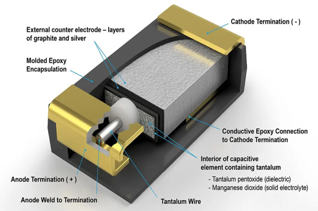
Tantalum pentoxide is the dielectric layer with semiconducting features that will only conduct current in one direction. In the reverse direction, an oxide layer readily grows under anodic conditions that act as a highly effective insulator. The anode is formed from pure tantalum powder to build a capacitor.

An oxide layer, typically Ta2O5, is grown as a dielectric and is then electrically connected using a solid or wet electrolyte. As shown in Figure 1, this material stackup can be packaged to form a high performance surface mount capacitor.

Tantalum capacitors are regarded highly in the electrolytic capacitors family for their large capacitance per unit volume and generally stable operating characteristics. They exhibit self-healing properties and typically provide low electrical series resistance (ESR) with favorable AC impedance characteristics.

For these reasons, the two primary applications of tantalum capacitors in circuit design have been as high capacity energy storage elements and as ripple filtering components in power supplies.

Niobium Oxide NbO Capacitors

Figure 2: Niobium capacitor construction layers. Image courtesy of KYOCERA AVX

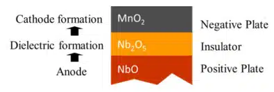
Much like their tantalum counterparts, niobium oxide capacitors are constructed using the anode, oxide, electrolyte construction. The anode material is typically passivated niobium or niobium monoxide. The dielectric is grown as niobium pentoxide, and the solid electrolyte is composed of manganese dioxide, as shown in Figure 2.

Like tantalum capacitors, niobium capacitors exhibit many favorable characteristics, including high volumetric capacitance, stable operating characteristics, and a self-healing mechanism for long-term reliability. In addition, when compared to tantalum, niobium is abundant and readily available as a raw material making the capacitor supply chain less susceptible to market fluctuations. Most importantly, niobium offers several properties that make its failure modes more graceful than comparable capacitors.

Failure Mode Comparison

Tantalum capacitors often find applications in filtering circuits where a large bulk capacitance is required. Unfortunately, these devices suffer from poor tolerance to large overages in voltage or current. A strong surge in current, a high ripple in current, or a high voltage across the circuit can quickly lead to failure. This is due mainly to the reactivity of the constituent metals with oxygen.

When a dielectric breakdown occurs, the heat generated by the large current passing through the defect site will cause the dielectric layer to be quickly destroyed. This, in turn, allows the pure tantalum anode to interact directly with oxygen at high temperatures. The resulting chemical reaction releases a significant amount of heat energy.

On the other hand, niobium capacitors use a niobium oxide anode, which is already oxygen rich and stable when exposed. During a dielectric breakdown event, the temperature rise is significantly lower than in the tantalum case. The niobium oxide layer tends to grow at elevated temperatures, resulting in a “self-arresting” mechanism. The benefit is a reduction (up to 95%) of the ignition failure mode of niobium oxide capacitors when compared to conventional tantalum devices. For this reason, niobium oxide capacitors are regarded as one of the safest capacitor technologies on the market.

Switching to Niobium Oxide Capacitors for Certain Applications

Given the seriousness of the tantalum dielectric failure mode, certain applications such as automotive, health care, and military may find significant improvements in safety by switching to niobium-based devices. The stable sub-oxide and self-arresting mechanism alone may offset any performance losses from parasitic resistance and inductance.

When used for switching power supply circuits, the niobium oxide capacitor does not need to be derated in voltage to the same degree as their Tantalum counterparts. High reliability can be achieved with no derating factor when resistance protection is added.

KYOCERA AVX offers a wide range of niobium oxide capacitors under OxiCap® trade name with high-reliability levels of 0.5%/1000hrs at 85°C or better, high safety technology with non-burning high resistance failure mode, and high break-down voltage. The OxiCap® series is available as low ESR, High CV, low profile, up to 125°C, and multi-anode technologies. It is environmentally friendly and
RoHS compliant technology in the same form, case size, and same or similar technical performance as standard tantalum capacitors. Capacitors are offered in voltage ratings up to 10V, and a majority of the series meet AEC-Q200 requirements.

Further reference links with more detailed tech information:

  • Niobium and Niobium Oxide Capacitors Overview
  • Tantalum and Niobium Capacitors

Related

Source: KYOCERA AVX

Recent Posts

Non-Linear MLCC Class II Capacitor Measurements Challenges

19.8.2025
7

Researchers Demonstrated HfO Anti-Ferroelectric Flexible Capacitors

19.8.2025
6

High Voltage MLCCs Meeting the Growing Demand for Efficiency in Power Conversion

12.8.2025
92

KYOCERA AVX Releases Hermaphroditic WTW and WTB Connectors

8.8.2025
13

Radiation Tolerance of Tantalum and Ceramic Capacitors

8.8.2025
67

TDK Releases Compact Polypropylene Film Capacitors for Resonant Topologies

7.8.2025
32

Root Causes and Effects of DC Bias and AC in Ceramic Capacitors

6.8.2025
53

Knowles Unveils High-Performance Safety-Certified MLCC Capacitors

6.8.2025
41

How to Calculate the Output Capacitor for a Switching Power Supply

6.8.2025
49

Evaluation and Modeling of Supercapacitors for Reliability of Lifetime Predictions

4.8.2025
35

Upcoming Events

Aug 20
16:00 - 16:30 CEST

Pulse transformer design for RLC loads

Aug 27
17:00 - 18:00 CEST

Capacitor Assemblies for High-Power Circuit Designs

Sep 3
15:30 - 17:30 CEST

How to Choose Your Magnetic Supplier

Sep 16
17:00 - 18:00 CEST

EMI Shielding Challenges

Sep 22
September 22 @ 13:00 - September 25 @ 15:15 EDT

Pre Cap Visual Inspection per Mil-Std-883 (TM 2017)

View Calendar

Popular Posts

  • Buck Converter Design and Calculation

    0 shares
    Share 0 Tweet 0
  • Boost Converter Design and Calculation

    0 shares
    Share 0 Tweet 0
  • Flyback Converter Design and Calculation

    0 shares
    Share 0 Tweet 0
  • LLC Resonant Converter Design and Calculation

    0 shares
    Share 0 Tweet 0
  • What is a Dielectric Constant and DF of Plastic Materials?

    4 shares
    Share 4 Tweet 0
  • Ripple Current and its Effects on the Performance of Capacitors

    3 shares
    Share 3 Tweet 0
  • Dual Active Bridge (DAB) Topology Explained

    0 shares
    Share 0 Tweet 0
  • How to Design an Inductor

    0 shares
    Share 0 Tweet 0
  • MLCC Case Sizes Standards Explained

    0 shares
    Share 0 Tweet 0
  • MLCC and Ceramic Capacitors

    0 shares
    Share 0 Tweet 0

Newsletter Subscription


Passive Components Blog

© EPCI - Leading Passive Components Educational and Information Site

  • Home
  • Privacy Policy
  • EPCI Membership & Advertisement
  • About

No Result
View All Result
  • Home
  • Knowledge Blog
  • Premium Suppliers

© EPCI - Leading Passive Components Educational and Information Site

This website uses cookies. By continuing to use this website you are giving consent to cookies being used. Visit our Privacy and Cookie Policy.
Go to mobile version