


This article explains operation principles, features and packaging options of thermistors.
Key Takeaways
- Thermistors are temperature-sensitive resistors that change resistance significantly with temperature, enabling temperature measurement and protection functions.
- They exist mainly as NTC (Negative Temperature Coefficient) and PTC (Positive Temperature Coefficient) thermistors, each serving different applications.
- NTC thermistors use materials like doped metal oxide ceramics and exhibit an exponential resistance change with temperature; meanwhile, PTC thermistors act as resettable fuses under over-current conditions.
- The choice of thermistor packaging and geometry strongly impacts performance, with options ranging from beads to discs and SMD chips for various applications.
- Designers must consider key parameters such as tolerances, thermal response, and electrical behavior when selecting thermistors for electronic systems.
Introduction to thermistors
Thermistors are temperature‑sensitive resistors whose resistance changes strongly with temperature and that are made from semiconducting ceramic or polymer materials. They are widely used for temperature measurement and compensation (mainly NTC) and for over‑current and over‑temperature protection (mainly PTC). Compared to RTDs and semiconductor temperature sensors, thermistors offer very high sensitivity, small size, and low cost, at the expense of non‑linearity and more limited absolute accuracy.
Thermistors can be broadly divided into:
- NTC thermistors (Negative Temperature Coefficient): resistance decreases exponentially with temperature; used mainly as temperature sensors and inrush current limiters.
- PTC thermistors (Positive Temperature Coefficient): resistance increases sharply above a transition temperature or fault current; used mainly as resettable protection devices and self‑regulating heaters.
Overview and classification
The table below puts thermistors into context with other temperature‑sensitive devices.
Table 1 – Common temperature‑sensing and protection devices
| Technology | Typical role | Linearity | Accuracy (typical) | Temperature range | Cost |
|---|---|---|---|---|---|
| NTC | Sensing, compensation, inrush | Poor | Medium | −40 to 150/200 °C | Low |
| PTC | Protection, self‑regulating | Poor | Threshold‑oriented | −40 to 125/150 °C | Low |
| RTD | Precision temperature sensing | Good | High | −200 to 600 °C | High |
| IC sensor | Easy interface, monitoring | Good | Medium–high | −40 to 125/150 °C | Medium |
| Fuse | One‑shot over‑current protection | N/A | N/A | Current protection only | Low |
| PPTC | Resettable over‑current protection | N/A | Threshold‑oriented | Current protection only | Low |
Construction and designs
Thermistor materials are based on doped metal oxide ceramics or conductive polymer composites. These materials are pressed, sintered or extruded into the desired shape and then encapsulated. Terminals are either inserted into the body or soldered to metallized surfaces, and the body is often coated with lacquer, epoxy, glaze or glass to improve robustness and moisture resistance.
Common geometries include rods, discs and beads, often encapsulated, as well as SMD chip thermistors. Low‑ohmic SMD NTCs may use multiple internal electrodes to create several resistor elements in parallel inside one body, reducing resistance without increasing footprint. PTC thermistors exist as multilayer chips, MELF cylinders, radial or axial leaded parts, probe assemblies, and special rods or discs for heating functions.
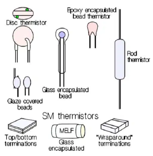
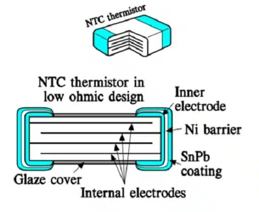
Table 2 – Typical thermistor geometries
| Geometry / package | Typical type | Typical use | Notes |
|---|---|---|---|
| Bead | NTC | Fast sensors, probes | Very small, fragile |
| Disc | NTC/PTC | Power NTC, PTC heaters, inrush | Higher energy capability |
| SMD chip | NTC/PTC | PCB‑mounted sensors/protectors | Automated assembly |
| MELF | PTC | Automotive, industrial protection | Robust, cylindrical |
| Radial leaded | NTC/PPTC | Inrush limiters, resettable fuses | Through‑hole |
| Axial leaded/strap | PPTC/NTC | Battery packs, surface mounting | Direct contact to surfaces |
| Probe assemblies | NTC/PTC | HVAC, appliances, industrial | Customized housing and leads |
NTC thermistor basics
NTC thermistors are based on doped semiconducting oxides whose conductivity increases with temperature. Their resistance follows an exponential temperature dependence typically expressed by the Steinhart–Hart‑type relation:
where A sets the nominal resistance level and determines the temperature dependence.
For practical use, the relationship between a reference temperature (usually 20 or 25 °C) and a general temperature is often written as:
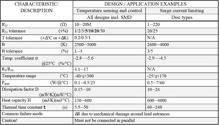
The constant (B‑value) is determined from measurements at two temperatures, often 25 °C and 50 °C, and typically lies between 2500 K and 5000 K depending on material and application.
NTC tolerances and R/T curves
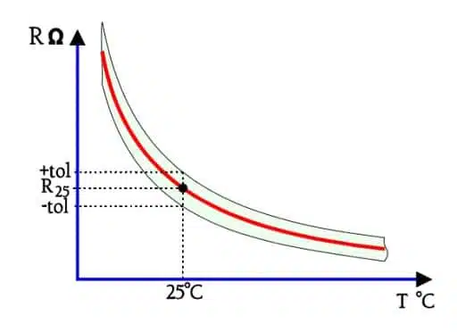
Manufacturing involves strong shrinkage of the sintered material, which makes it challenging to control both the nominal resistance and the B‑value tightly. Standard tolerances for B may be around 5%, while nominal resistance at 25 °C is often specified with 5, 10 or 20% tolerance. Through precision machining of already‑sintered chips, much tighter tolerances down to 0.2–1% on and about 1% on B are achievable.
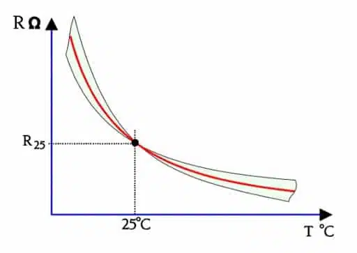
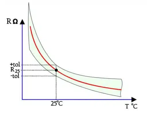
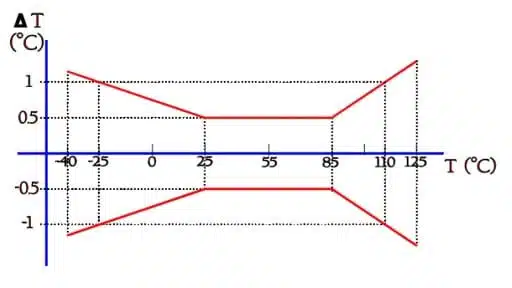
The combination of and B tolerances defines a tolerance band for the resistance–temperature (R/T) curve, often illustrated as a family of curves around the nominal characteristic. For higher‑accuracy sensing, sensors may be specified by tracking one or more points on the R/T curve, and tolerances can then be expressed either as resistance deviation ∆R or as equivalent temperature deviation ∆T at those points.
NTC slope and temperature coefficient
The slope of the R/T curve is directly related to the B‑value and can be expressed by the temperature coefficient , defined as:
For NTC thermistors, is negative and varies with temperature; around 25 °C, typical values are between −3%/°C and −5.5%/°C. Designers sometimes also use resistance ratios, such as or , which characterize the curve shape and can be specified with tolerances.
Table 3 – Typical NTC parameter ranges (illustrative)
| Parameter | Typical value / range |
|---|---|
| Nominal resistance R25 | 1 kΩ to 1 MΩ |
| B‑value | 2500 K to 5000 K |
| Tolerance on R25 | ±0.2% to ±20% |
| Tolerance on B | ±1% to ±5% |
| Temperature coefficient | −3 to −5.5%/°C at 25 °C |
NTC self‑heating and V–I behavior
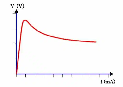
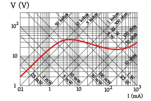
When a voltage is applied across an NTC thermistor, current initially follows Ohm’s law. As power dissipation heats the body, the resistance drops, increasing current further and causing a characteristic bending of the V–I curve. At higher voltages, the resistance decreases faster than the current rises, and the V–I graph may show a region where incremental resistance is negative.
This self‑heating behavior can be either an error source in temperature sensing (if measurement current is too high) or an intentional operating mode in applications such as inrush current limiting and self‑heated flow sensors.
Thermal time constant and dissipation factor
The temperature response of a thermistor is characterized by:
- Thermal time constant t: time required for the thermistor to reach 63.2% of the total temperature change when subjected to a step change in ambient temperature under zero power.
- Heat capacity (J/°C): energy needed to raise the thermistor body by 1 °C.
- Dissipation factor (mW/°C): power that raises the thermistor’s mean temperature by 1 °C when freely mounted in still air.
These parameters are related by:
Smaller chips and bead thermistors have low heat capacity and short time constants, especially when immersed in liquids, while larger discs or encapsulated probes have higher heat capacity and slower response.
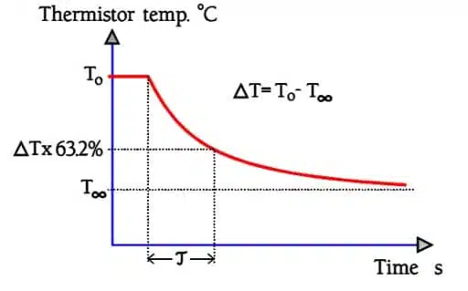
Table 4 – Typical NTC thermal parameters (illustrative)
| Package type | Time constant (air) | Time constant (liquid) | Dissipation factor (air) |
|---|---|---|---|
| Bead | 0.3–2 s | 0.05–0.3 s | 0.5–2 mW/°C |
| SMD 0603 | 2–5 s | 0.2–1 s | 1–3 mW/°C |
| Disc, coated | 5–20 s | 1–5 s | 2–10 mW/°C |
| Probe | 5–60 s | 1–20 s | Application‑dependent |
NTC application modes and type selection
NTC thermistors are used in three broad modes:
- Temperature sensing: resistance as a function of environmental temperature under low measurement current.
- Self‑heated operation: resistance as a function of self‑heating, for example in inrush current limiters and flow sensors.
- Time‑dependent behavior: resistance as a function of time, exploiting thermal inertia in delay circuits.
When selecting an NTC, designers consider:
- Encapsulation and environment: glass, glaze, epoxy/lacquer, or uncoated.
- Temperature range and thermal shock/humidity requirements.
- Geometry: SMD chip, rod, disc, bead, or custom probe.
- Mounting method: soldering, welding, bonding, or mechanical clamping.
- Reference resistance R25 and desired sensitivity (B‑value or temperature coefficient).
- Tolerance requirements at one or multiple temperatures (point matching vs curve tracking).
- Power dissipation limits and acceptable self‑heating.
- Thermal time constant suitable for the application dynamics.
NTC linearization and interface circuits
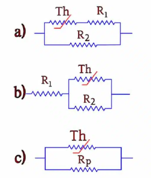
Because the R/T curve is highly non‑linear, simple linearization techniques with fixed resistors are often employed. Common approaches include series and parallel resistors or voltage‑divider configurations that flatten the response in the temperature band of interest. For example, placing a resistor in parallel with the NTC can be dimensioned so that the combined resistance intersects a straight line at three temperatures, resulting in a near‑linear response over a limited range.
Typical interface circuits include:
- Voltage divider with NTC and fixed resistor feeding an ADC input, with the ratio chosen to maximize resolution near the critical temperature range.
- Bridge circuits for higher‑precision measurement and drift compensation.
- Simple threshold circuits using comparators if only an over/under‑temperature indication is needed.
Measurement current must be chosen low enough to keep self‑heating errors within the permissible accuracy budget.
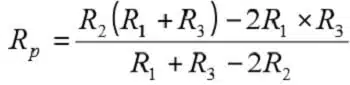
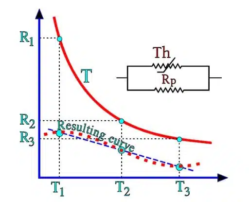
Table 5 – Simple NTC voltage divider design steps
| Step | Action |
|---|---|
| 1 | Choose nominal at mid‑range temperature |
| 2 | Select fixed resistor ≈ at mid‑range |
| 3 | Calculate divider voltage at min, mid, max T |
| 4 | Check ADC range and resolution |
| 5 | Adjust resistor value or supply/reference as needed |
NTC failure modes and reliability
NTC thermistors are small and high‑resistance components whose performance is sensitive to material and mechanical imperfections. Vulnerable areas include the lead–body interface, especially in unencapsulated or thinly coated discs and beads. Mechanical stress from improper lead forming can create micro‑cracks that both change resistance and allow moisture ingress, leading to drift or intermittent failures.
The sintered material can undergo crystalline settling, manifesting as sudden resistance jumps of a few percent triggered by thermal or mechanical shocks; burn‑in heat treatment is used to stabilize these effects. Hermetically sealed glass‑encapsulated beads and SMD thermistors have significantly improved mechanical robustness and moisture resistance, and their reliability is comparable to that of ceramic chip capacitors and thick‑film resistors when sourced from qualified manufacturers. NTC thermistors are not suitable for parallel connection to increase power rating because the element with slightly lower resistance will self‑heat more, further lowering its resistance and leading to thermal runaway and failure.
Table 6 – Typical NTC failure mechanisms
| Mechanism | Cause | Symptom |
|---|---|---|
| Micro‑cracks | Lead forming, mechanical shock | Drift, intermittent opens |
| Moisture ingress | Damaged coating | Gradual resistance drift |
| Crystalline settling | Thermal or mechanical shock | Sudden step in resistance |
| Overload/overheat | Operation beyond ratings | Permanent resistance change |
| Parallel operation | Unequal self‑heating | Thermal runaway, burnout |
NTCs in special environments
Tests with neutron, beta and gamma radiation have shown that thermistors can withstand high levels of nuclear radiation with negligible changes in electrical characteristics. This makes them suitable for use in harsh environments such as nuclear instrumentation and space applications, provided other components and insulation systems are also rated appropriately.
PTC thermistors: roles and principles
PTC thermistors with positive temperature coefficient behavior are mainly used for over‑current and over‑temperature protection, as well as in self‑regulating heater and degaussing circuits. Two major technologies exist:
- Ceramic PTC thermistors based on doped barium titanate with a ferroelectric transition (Curie point).
- Polymer PTC (PPTC) thermistors based on conductive particles dispersed in a polymer matrix.
In both technologies, resistance remains relatively low in the normal operating range, then increases sharply by several orders of magnitude when a threshold temperature is exceeded, creating a switch‑like behavior.
Ceramic PTC thermistor technology
Ceramic PTC thermistors use doped barium titanate ceramics with additives such as magnesium or strontium to tailor resistivity and transition temperature. Below the Curie point, the material exhibits low resistance with a small negative temperature coefficient, but as temperature approaches the Curie point, changes in dielectric constant increase barriers between grains and restrict electron flow, causing a steep rise in resistivity. Above the transition, resistance can increase exponentially by several decades with temperature.
Ceramic PTCs are considered robust and reliable and have been widely used for degaussing circuits in CRT televisions and monitors, inrush current limiting, motor start assistance, and as temperature sensors in probe assemblies for HVAC and household appliances.
Polymer PTC (PPTC) technology
Polymer PTC devices are made from a polymer matrix loaded with conductive particles such as carbon black. At normal temperatures, the polymer is in a relatively compact phase where conductive particles are in close contact, providing a low‑resistance path. When temperature rises above the material’s transition point due to ambient heating or I²R self‑heating under fault current, the polymer expands, breaking many conduction paths and causing a sharp increase in resistance.
PPTCs typically have lower base resistivity than ceramic PTCs, which allows them to carry higher normal currents for a given size. Their lower production cost and resettable fuse behavior have driven widespread adoption in electronics for over‑current protection.
Ceramic vs polymer PTC: technology differences
Ceramic PTC thermistors support both protection functions and application‑specific roles such as degaussing, self‑regulating heating, and motor or ballast inrush limiting. Polymer PTCs are primarily used for over‑current and over‑temperature protection where a resettable fuse is desired.
Ceramic PTCs can be fabricated as multilayer chips, enabling very small case sizes down to 0201 and even 01005, similar to MLCCs and thick‑film resistors. Polymer PTCs are produced from extruded polymer sheets, so their performance is more closely tied to surface area, historically leading to larger physical sizes for similar hold currents, though newer PPTC chips continue to shrink and are now available down to small SMD case sizes.
Production cost is generally lower for PPTCs due to simpler material systems and processes, giving them an advantage where price is critical and extreme robustness or special functions are not required.
Table 7 – Ceramic PTC vs PPTC overview
| Feature | Ceramic PTC | Polymer PTC (PPTC) |
|---|---|---|
| Base material | Doped BaTiO₃ ceramic | Polymer + conductive filler |
| Main function | Protection, heating | Resettable over‑current |
| Size potential | Down to 01005 chip | Limited by sheet geometry |
| Cost level | Medium | Low |
| Energy handling | High (discs, rods) | Moderate |
| Typical markets | Appliances, industrial, automotive | Consumer, ICT, low‑voltage |
PTC manufacturing processes
Ceramic PTC process:
- Doped barium titanate is prepared as a powder, milled and mixed into a slurry.
- For leaded parts, discs are pressed, lead wires attached, silver electrodes applied, and the assembly is fired in a kiln.
- A protective epoxy or glass coating is applied for environmental protection.
- For chip devices, stacked green ceramic sheets with printed internal electrodes are laminated, fired, and diced into multilayer chips with terminations applied.
Polymer PTC process:
- A polymer is loaded with carbon black and mixed to the appropriate viscosity.
- The mixture is extruded into thin sheets and cross‑linked (for example by irradiation) to stabilize the structure.
- Sheets are cut into the desired shapes, electrodes or terminations are attached, and radial parts are typically epoxy‑coated.
PTC package configurations
Ceramic PTC configurations include:
- Multilayer chip thermistors for PCB mounting.
- MELF cylindrical surface‑mount designs favored in automotive applications.
- Radial and axial leaded parts for over‑current and temperature protection.
- Bare rods and discs used as heating elements or in customized housings.
- Probe assemblies that integrate a PTC into a metal tube or custom sensor.
Polymer PTC configurations include:
- Square and round radial‑leaded devices for telecom line protection and industrial electronics.
- Surface‑mount PPTC chips for portable and computer applications where board space is limited.
- Axial strap types for direct mounting on battery cells, especially in rechargeable pack protection.
PTC electrical behavior and datasheet parameters
Key PTC/PPTC electrical parameters include:
- Hold current (IHOLD): maximum continuous current at a specified ambient temperature for which the device remains in its low‑resistance state.
- Trip current (ITRIP): current at which the device will switch to its high‑resistance state within a specified time.
- Maximum operating voltage and fault current: limits beyond which damage or unsafe operation may occur.
- Initial resistance and resistance in the tripped state: important for insertion loss and fault behavior.
- Time‑to‑trip vs current and ambient temperature derating: curves showing how trip performance varies over temperature.
These parameters, combined with R(T) curves for ceramic PTCs with a pronounced Curie point, allow engineers to select devices for over‑current protection or temperature‑limiting roles.
Table 8 – Typical PPTC datasheet entries
| Parameter | Description |
|---|---|
| IHOLD | Hold current at 25 °C |
| ITRIP | Trip current at 25 °C |
| Vmax | Maximum operating voltage |
| Imax | Maximum fault current |
| Rmin/Rmax | Initial resistance range at 25 °C |
| R1max | Maximum resistance one hour after trip |
| Pd typ | Typical power dissipation in hold state |
PTC selection and application examples
Typical application patterns include:
- PPTC in series with a low‑voltage supply rail (for example USB or logic rails) to protect against short circuits and overloads.
- PTC thermistor in series with motor windings or transformers to limit current during start‑up and to provide protection during stall or over‑temperature conditions.
- Ceramic PTC elements in degaussing circuits of CRT displays and in self‑regulating heater elements where the high‑temperature resistance limits maximum temperature without external control.
Selection involves choosing IHOLD above the maximum normal operating current but below fault levels, ensuring ITRIP and time‑to‑trip meet system protection requirements, and verifying voltage and energy ratings are adequate for worst‑case conditions.
Table 9 – Example PTC application guidelines
| Application | Key selection focus |
|---|---|
| USB rail protection | IHOLD > max load, ITRIP < fault level |
| Battery pack | Strap type, good thermal coupling |
| Motor winding | Ceramic PTC with suitable Curie T |
| Degaussing/heating | Disc/rod with required power and T |
PTC reset behavior, aging and limitations
After a trip event, PTC and PPTC devices cool and return to their low‑resistance state, but the recovery time depends on ambient conditions and thermal mass. Frequent or prolonged trips can lead to gradual increases in base resistance and changes in trip characteristics, especially in polymer devices due to structural changes over life. Designers must account for ambient temperature influence on IHOLD and ITRIP to avoid nuisance tripping, particularly in high‑temperature environments.
Ceramic PTCs used as heaters or in repeated degaussing cycles are generally robust but may experience changes in resistance after very long life or severe thermal cycling. PPTCs are attractive because they are resettable, but they do not replace fuses in all applications, particularly where precise, predictable trip behavior over life is required.
Packaging, mounting and thermal interface
Across both NTC and PTC types, package choice strongly impacts performance. Beads and small chips offer fast response but are mechanically fragile. Discs and rods handle higher energy. Coated or glass‑sealed parts improve moisture resistance. Probes provide robust mechanical mounting and controlled thermal coupling to pipes, surfaces or air streams.
Good thermal interface design is critical. Sensors used for temperature measurement should have low thermal resistance to the measured medium but appropriate electrical insulation. Protection devices must be mounted so that they sense the relevant temperature or current‑induced heating and can safely dissipate fault energy.
Comparison with other technologies
Thermistors compete and complement other technologies:
- RTDs: higher absolute accuracy and linearity over a wide range but larger and more expensive.
- Semiconductor temperature sensors: convenient linear voltage or digital output, but limited high‑temperature range and typically slower thermal response.
- Fuses and circuit breakers: precise, often single‑shot over‑current protection, whereas PPTCs provide resettable but less sharply defined trip behavior.
Thermistors are preferred where high sensitivity, small size, low cost, and resettable behavior (for PTC/PPTC) are more important than absolute accuracy or perfectly defined trip points.
Reliability and standards
Modern thermistors, especially SMD NTCs and multilayer ceramic PTCs from qualified manufacturers, demonstrate reliability comparable to other passive components when used within ratings and with appropriate environmental protection. Burn‑in, statistical process control, and moisture‑resistant encapsulations have greatly improved stability. Designers should verify applicable standards or qualification requirements (for example automotive, appliance safety, or telecom) and check that chosen components and probe assemblies are approved accordingly.
Summary
This article provides a complete introduction to thermistors, explaining how their resistance varies strongly with temperature and why this makes them useful for sensing, compensation and protection functions in electronic systems. It distinguishes NTC thermistors, used mainly for temperature measurement and inrush‑current limiting, from PTC and polymer PTC devices, which are primarily used as resettable over‑current and over‑temperature protectors or self‑regulating heaters.
The text describes thermistor materials, construction and packaging, including beads, discs, SMD chips, MELF parts, radial/axial leaded devices and probe assemblies, and links these geometries to typical applications and energy‑handling capabilities. For NTCs, it covers the exponential R–T characteristic, B‑value, tolerances, temperature coefficient, self‑heating effects, thermal time constant and dissipation factor, as well as linearization techniques, application modes and typical failure mechanisms. For PTCs, it explains ceramic and polymer technologies, manufacturing processes, electrical parameters such as IHOLD and ITRIP, and how these components are applied in power rails, motors, degaussing circuits and battery packs.
Conclusion
NTC and PTC thermistors together form a versatile family of temperature‑dependent resistors that can address both precise sensing tasks and robust protection functions when their characteristics are properly understood and applied. By linking material physics, geometry, thermal behavior and key datasheet parameters to concrete circuit roles, the article gives designers practical guidance for selecting suitable thermistor types, packages and interface circuits across consumer, industrial, automotive and specialty applications.
FAQ about Thermistors, NTC and PTC
A thermistor is a temperature‑sensitive resistor whose resistance changes significantly with temperature, enabling accurate temperature sensing, compensation and protection in electronic circuits. It is typically made from semiconducting ceramic or polymer materials that exhibit a strong, non‑linear resistance–temperature characteristic.
NTC thermistors have a negative temperature coefficient, so their resistance decreases exponentially as temperature rises, which makes them ideal for temperature measurement and compensation. PTC thermistors have a positive temperature coefficient and show a sharp increase in resistance above a threshold temperature or fault current, so they are mainly used for resettable over‑current and over‑temperature protection.
NTC thermistors are widely used in HVAC, appliances, industrial and automotive systems for temperature sensing, compensation and inrush‑current limiting. PTC and PPTC devices are used in power supplies, motors, telecom lines, battery packs and degaussing or self‑regulating heater circuits for protection and current limiting.
Selection focuses on the application (sensing vs protection), geometry and package, operating temperature range, and key electrical parameters such as R25, B‑value, tolerances and thermal time constant for NTCs, or IHOLD, ITRIP, voltage rating and time‑to‑trip for PTCs. Designers also consider mounting method, environmental robustness and required response time to match system requirements.
Compared to RTDs and IC sensors, thermistors offer very high sensitivity, small size and low cost, which is attractive in compact and cost‑sensitive designs. The trade‑offs are non‑linear characteristics, limited absolute accuracy without calibration and narrower usable temperature ranges than precision RTDs.
Modern SMD NTCs and multilayer ceramic PTCs from qualified manufacturers show reliability comparable to other passive components when used within their ratings and with suitable encapsulation. They can even operate reliably under conditions such as high humidity, thermal cycling and, for special types, elevated radiation levels, provided the overall design and insulation system are properly engineered.
How to choose and apply NTC and PTC thermistors in your design
- Step 1 – Define the thermistor function
Choose between sensing and protection
Decide whether the component will primarily measure temperature (for example for monitoring or compensation) or protect against over‑current and over‑temperature events. Use NTC thermistors for measurement and temperature‑dependent control, and use PTC or PPTC devices where resettable current limiting or temperature limiting is required. - Step 2 – Select NTC or PTC type and geometry
Match technology and package to the application
For NTC sensing, choose between beads, SMD chips, discs or probes depending on required response time, mechanical robustness and mounting method. For PTC/PPTC protection, select chip, radial, MELF or strap types that can handle the expected current, energy and mechanical constraints in your layout. - Step 3 – Check key datasheet parameters
Understand electrical and thermal ratings
For NTCs, review nominal resistance R25, B‑value, tolerances, operating temperature range, power rating, dissipation factor and thermal time constant so you can predict accuracy and response. For PTC/PPTC devices, check IHOLD, ITRIP, maximum operating voltage, maximum fault current, initial and tripped resistance, and derating curves versus ambient temperature. - Step 4 – Design the interface circuit
Implement simple sensing or protection circuits
For NTC temperature measurement, implement a voltage divider or bridge circuit that feeds an ADC, choosing the series resistor to optimize resolution over the critical temperature range and limiting measurement current to avoid self‑heating. For PTC/PPTC protection, place the device in series with the protected line so that fault current self‑heats the element into its high‑resistance state, and verify that normal operating current remains below IHOLD under all temperature conditions. - Step 5 – Consider mounting, environment and reliability
Ensure good thermal coupling and long‑term stability
Mount thermistors to achieve good thermal contact with the medium being sensed or the component being protected while maintaining adequate electrical insulation and creepage distances. Choose encapsulation, coating and package style appropriate for humidity, vibration and thermal cycling, and avoid mechanical stress on leads or terminations to prevent drift and premature failures.