Passive Components Blog
No Result
View All Result
  • Home
  • NewsFilter
    • All
    • Aerospace & Defence
    • Antenna
    • Applications
    • Automotive
    • Capacitors
    • Circuit Protection Devices
    • electro-mechanical news
    • Filters
    • Fuses
    • Inductors
    • Industrial
    • Integrated Passives
    • inter-connect news
    • Market & Supply Chain
    • Market Insights
    • Medical
    • Modelling and Simulation
    • New Materials & Supply
    • New Technologies
    • Non-linear Passives
    • Oscillators
    • Passive Sensors News
    • Resistors
    • RF & Microwave
    • Telecommunication
    • Weekly Digest

    TDK Introduces High‑Voltage Common‑Mode Chokes for Compact 1250 V DC Converters

    Vishay Extends Power Inductors for DC/DC with 1212 Compact Case

    Modeling Planar Magnetics Temperature: Practical Guidelines for Power Electronics Engineers

    YAGEO Releases Ferrite Shielded Power Inductors for High‑Density Designs

    Samsung Presents MLCC Selection Guide for Humanoids and Robotic Applications

    AI-Assisted Structural Diagnostics and Physics-Based Reliability Interpretation of Tantalum Capacitor Anodes

    YAGEO Introduces EMI Suppression High‑Current 3‑phase Common Mode Chokes

    KYOCERA AVX MIL-PRF-32535 BME NP0 MLCCs Approved to the DLA QPD

    ECIA March 2026 Industry Pulse Points to Best Sales Climate in Five Years

    Trending Tags

    • Ripple Current
    • RF
    • Leakage Current
    • Tantalum vs Ceramic
    • Snubber
    • Low ESR
    • Feedthrough
    • Derating
    • Dielectric Constant
    • New Products
    • Market Reports
  • VideoFilter
    • All
    • Antenna videos
    • Capacitor videos
    • Circuit Protection Video
    • Filter videos
    • Fuse videos
    • Inductor videos
    • Inter-Connect Video
    • Non-linear passives videos
    • Oscillator videos
    • Passive sensors videos
    • Resistor videos

    Transformer-Based Power-Line Harvester Magnetic Design

    Thermal Modeling of Magnetics

    Standard vs Planar LLC transformers Comparison for Battery Chargers

    How Modern Tools Model Magnetic Components for Power Electronics

    Advanced Loss Modeling for Planar Magnetics in the Frenetic Planar Tool

    2026 Power Magnetics Design Trends: Flyback, DAB and Planar

    Enabling Software‑Defined Vehicle Architectures: Automotive Ethernet and Zonal Smart Power

    Calculating Resistance Value of a Flyback RC Snubber 

    One‑Pulse Characterization of Nonlinear Power Inductors

    Trending Tags

    • Capacitors explained
    • Inductors explained
    • Resistors explained
    • Filters explained
    • Application Video Guidelines
    • EMC
    • New Products
    • Ripple Current
    • Simulation
    • Tantalum vs Ceramic
  • Knowledge Blog
  • DossiersNew
  • Suppliers
    • Who is Who
  • PCNS
    • PCNS 2025
    • PCNS 2023
    • PCNS 2021
    • PCNS 2019
    • PCNS 2017
  • Events
No Result
View All Result
Passive Components Blog
No Result
View All Result

Vishay Extends Power Inductors for DC/DC with 1212 Compact Case

16.4.2026
Reading Time: 8 mins read
A A

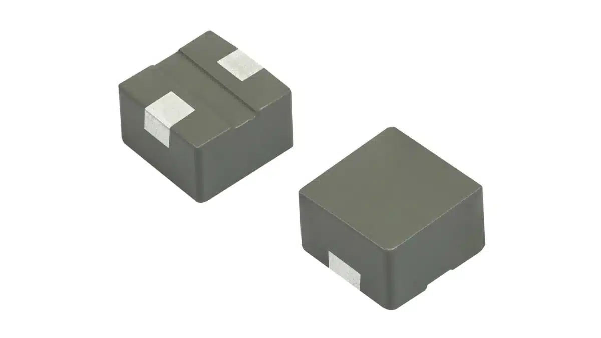
Vishay’s new IHLP1212‑EZ‑1Z power inductors bring the well‑known IHLP low‑profile, high‑current technology into a very compact 1212 case size (3.0 mm × 3.0 mm) with multiple height options.

These Vishay shielded, low DCR power inductors are aimed at space‑constrained commercial power electronics, where designers need high efficiency, robust EMI performance, and reliable operation over a wide temperature range.

RelatedPosts

Vishay Releases 2-Way Wilkinson Divider / Combiner for 15–20 GHz RF Front Ends

Vishay Releases Compact High‑Accuracy Hall Effect Linear Position Sensor

Vishay Introduced Space-Grade SMT Common Mode Choke

Key features and benefits

The IHLP1212‑EZ‑1Z inductors extends the IHLP family into smaller form factors while keeping key performance characteristics needed in modern DC/DC converters and noise suppression filters.

Form factor and construction

  • 1212 case size, with a 3.0 mm × 3.0 mm footprint for very dense board layouts.
  • Three profile options: 1.2 mm, 1.5 mm, and 2.0 mm overall height, enabling fine optimization between current rating and available z‑height in the system.
  • Powdered iron core body completely encapsulates the windings, with no air gaps and magnetic shielding for reduced crosstalk to nearby components.
  • 100% lead‑free, shielded composite construction designed to reduce acoustic buzz to ultra‑low levels.

Electrical performance

  • Inductance range from 0.22 µH up to 3.3 µH, depending on height option.
  • Typical DCR from 8.6 mΩ to 50.4 mΩ, supporting high efficiency in low‑voltage, high‑current rails.
  • Rated current up to 14.3 A (depending on inductance value and height).
  • Self‑resonant frequency (SRF) up to 214 MHz, which is beneficial for switching regulators operating in the several‑MHz range.

Thermal and reliability characteristics

  • Operating temperature range from −55 °C to +125 °C, suitable for many industrial and commercial environments.
  • High resistance to thermal shock, moisture, and mechanical shock, contributing to long‑term reliability in demanding applications.
  • Soft saturation curve, which helps maintain inductance and stable behavior over the entire operating current and temperature range.

Compliance and environmental aspects

  • RoHS‑compliant, halogen‑free, and classified as Vishay Green for environmentally conscious designs.

For many DC/DC converter topologies, this combination of low DCR, wide inductance range, and compact footprint directly translates into lower copper losses, improved efficiency, and smaller overall power stage size.

Family‑level specification overview

Parameter1.2 mm profile1.5 mm profile2.0 mm profile
Case size1212 (3.0 × 3.0 mm)1212 (3.0 × 3.0 mm)1212 (3.0 × 3.0 mm)
Inductance range (µH)0.22 – 1.00.22 – 1.50.22 – 3.3
Typical DCR range (mΩ)8.6 – 29.48.6 – 36.98.6 – 50.4
Max DCR range (mΩ)10.3 – 33.810.3 – 41.410.3 – 54.9
Heat‑rating current range (A)6.1 – 11.15.5 – 11.14.5 – 11.1
Saturation current range (A)5.1 – 9.5 / 6.7 – 12.4 (20/30% drop)5.0 – 11.0 / 6.5 – 14.3 (20/30% drop)3.7 – 10.5 / 4.8 – 13.7 (20/30% drop)
SRF range (MHz)66 – 18551 – 20230 – 214

Interpretation of key ratings (according to manufacturer datasheet terminology):

  • Heat‑rating current is the DC current that causes an approximate 40 °C temperature rise above ambient. In practice, this is a thermal design limit and helps ensure that hot spot temperatures remain within the allowed component and system range.
  • Saturation current is specified for two thresholds, the current that causes the initial inductance to drop by about 20% and 30% respectively. Designers typically choose the operating current so that peak ripple current stays below the 20% drop point for conservative designs, or within the 30% limit if some inductance roll‑off is acceptable.
  • The SRF values indicate where the inductor’s impedance transitions from inductive to capacitive behavior. For switching converters, the fundamental switching frequency is usually kept significantly below SRF to maintain clean inductive behavior.

Thanks to the powdered iron material and soft saturation, the inductance decreases gradually rather than abruptly when approaching the saturation current rating, which helps maintain stability under transient load steps or short‑term inrush events.

Typical applications

The IHLP1212‑EZ‑1Z is positioned for a broad range of commercial and industrial applications where board space is at a premium but current demands remain significant.

Typical use cases include:

  • Energy storage inductors in low‑profile DC/DC converters for
    • PMIC‑based point‑of‑load regulators on dense digital boards
    • DC/DC stages in SoC and FPGA power trees
  • Power line noise suppression in:
    • Computers and peripherals (motherboards, graphics cards, SSD controllers)
    • Consumer entertainment electronics (set‑top boxes, game consoles, smart TVs)
    • Home and building control systems (smart thermostats, security panels, HVAC controllers)
  • Filtering and energy storage in:
    • Industrial drives and tools (compact motor drives, cordless tools, PLC modules)
    • Telecom equipment (small line cards, base station modules, CPE devices)
    • Medical instrumentation (portable monitors, diagnostic equipment), where reliable, low‑noise power is critical

Because of the shielded, low‑profile design, the IHLP1212‑EZ‑1Z family fits particularly well in high‑density multilayer PCBs placed under heatsinks or in enclosures with tight mechanical constraints.

Design‑in notes for engineers

When designing the IHLP1212‑EZ‑1Z into DC/DC converters or noise filters, a few practical points help get the best balance of size, loss, and EMI performance.

1. Selecting inductance and current rating

  • For buck converters, the inductance value affects the ripple current and transient behavior. Lower inductance (towards 0.22 µH) allows faster transient response but increases ripple current and core losses; higher inductance reduces ripple but can increase size or DCR.
  • Within a given inductance value, choosing the taller profile (1.5 mm or 2.0 mm) typically offers lower DCR and/or higher current ratings, at the expense of z‑height. This can be critical under heatsinks or in thin products like compact networking equipment.
  • Use the heat‑rating current as a thermal reference, ensuring that the worst‑case RMS current plus ripple does not push the temperature rise beyond system limits.

2. Managing thermal performance

  • Although the family supports operation up to +125 °C, thermal design should account for ambient temperature, neighboring hot components, and airflow.
  • Place the inductor to benefit from airflow and copper spreading in the PCB; additional copper area under and around the pads lowers temperature rise.
  • In compact designs with several inductors in proximity (e.g., multi‑phase VRMs), maintain sufficient spacing to avoid thermal coupling.

3. EMI and layout considerations

  • The magnetically shielded construction helps reduce stray fields and crosstalk, but good layout practices remain essential.
  • Keep high‑di/dt loops (switch node to inductor to output capacitor and back) as small as possible to minimize radiated emissions.
  • If the inductor is used for input or output filtering, place it close to the associated capacitors and power devices to reduce parasitic inductance.

4. Mechanical and reliability aspects

  • The composite body is designed for high resistance to mechanical shock and thermal cycling, supporting applications such as portable tools, industrial drives, or field‑installed building controls.
  • For harsh environments, verify solder joint reliability and consider underfill or mechanical support if strong vibration is expected, even though the inductor itself is robust.

5. Qualification and documentation

  • The series is RoHS‑compliant, halogen‑free, and Vishay Green, which simplifies environmental compliance documentation for end equipment.
  • For safety‑critical or long‑lifetime applications (such as medical instrumentation or building automation), check the latest derating curves, endurance test data, and qualification reports in the official datasheet and quality documentation.

Source

The information in this article is based on the official Vishay Intertechnology press release and associated product information for the IHLP1212‑EZ‑1Z series, with additional independent commentary aimed at design engineers and component specifiers.

References

  1. Vishay IHLP1212‑EZ‑1Z press release
  2. Vishay IHLP1212‑EZ‑1Z product page and datasheet

Related

Recent Posts

TDK Introduces High‑Voltage Common‑Mode Chokes for Compact 1250 V DC Converters

16.4.2026
2

Modeling Planar Magnetics Temperature: Practical Guidelines for Power Electronics Engineers

15.4.2026
8

YAGEO Releases Ferrite Shielded Power Inductors for High‑Density Designs

15.4.2026
7

Samsung Presents MLCC Selection Guide for Humanoids and Robotic Applications

15.4.2026
11

YAGEO Introduces EMI Suppression High‑Current 3‑phase Common Mode Chokes

14.4.2026
18

ECIA March 2026 Industry Pulse Points to Best Sales Climate in Five Years

13.4.2026
27

Coilcraft Unveils Molded Power Inductors for High‑Current VRMs

8.4.2026
39

Littelfuse Presents Ultra-Miniature Half-Pitch SMT DIP Switches

7.4.2026
12

SCHURTER Releases Compact SMT DIP Switches

7.4.2026
11

Upcoming Events

Apr 21
16:00 - 17:00 CEST

Heatsink Solutions: Thermal Management in electronic devices

Apr 29
10:00 - 11:00 CDT

SEPIC Design Done Right

May 5
16:00 - 17:00 CEST

Understanding and Selecting Capacitors – Fundamentals, Technologies and Latest Trends

View Calendar

Popular Posts

  • Buck Converter Design and Calculation

    0 shares
    Share 0 Tweet 0
  • Boost Converter Design and Calculation

    0 shares
    Share 0 Tweet 0
  • Flyback Converter Design and Calculation

    0 shares
    Share 0 Tweet 0
  • LLC Resonant Converter Design and Calculation

    0 shares
    Share 0 Tweet 0
  • MLCC and Ceramic Capacitors

    0 shares
    Share 0 Tweet 0
  • Dual Active Bridge (DAB) Topology

    0 shares
    Share 0 Tweet 0
  • Capacitor Charging and Discharging

    0 shares
    Share 0 Tweet 0
  • Plastic Materials Dielectric Constant and DF

    4 shares
    Share 4 Tweet 0
  • MLCC Case Sizes Standards Explained

    0 shares
    Share 0 Tweet 0
  • Ripple Current and its Effects on the Performance of Capacitors

    3 shares
    Share 3 Tweet 0

Newsletter Subscription


Passive Components Blog

© EPCI - Leading Passive Components Educational and Information Site

  • Home
  • Privacy Policy
  • EPCI Membership & Advertisement
  • About

No Result
View All Result
  • Home
  • Knowledge Blog
  • PCNS

© EPCI - Leading Passive Components Educational and Information Site

This website uses cookies. By continuing to use this website you are giving consent to cookies being used. Visit our Privacy and Cookie Policy.
Go to mobile version