Passive Components Blog
No Result
View All Result
  • Home
  • NewsFilter
    • All
    • Aerospace & Defence
    • Antenna
    • Applications
    • Automotive
    • Capacitors
    • Circuit Protection Devices
    • electro-mechanical news
    • Filters
    • Fuses
    • Inductors
    • Industrial
    • Integrated Passives
    • inter-connect news
    • Market & Supply Chain
    • Market Insights
    • Medical
    • Modelling and Simulation
    • New Materials & Supply
    • New Technologies
    • Non-linear Passives
    • Oscillators
    • Passive Sensors News
    • Resistors
    • RF & Microwave
    • Telecommunication
    • Weekly Digest

    Molecular Memristor Shows Record 145 kH Emergent Inductance

    Planar vs Conventional Transformer: When it Make Sense

    Researchers Propose Next‑Gen Compact Memory Using Ultra-thin Ferroelectric Capacitors

    Nichicon ADN Automotive Hybrid Aluminum Capacitors Now Available in EMEA

    Wk 19 Electronics Supply Chain Digest

    Electrocaloric Multilayer Capacitors: Towards Quiet, Solid‑State Cooling Around Room Temperature

    High-Crystallinity Nanocrystalline Composites for MHz Chip Inductors

    European Components Distribution Shows Strong Q1 2026 Growth Amid Geopolitical Uncertainty

    Stackpole Expanded its AlN Thick Film Chip Resistors

    Trending Tags

    • Ripple Current
    • RF
    • Leakage Current
    • Tantalum vs Ceramic
    • Snubber
    • Low ESR
    • Feedthrough
    • Derating
    • Dielectric Constant
    • New Products
    • Market Reports
  • VideoFilter
    • All
    • Antenna videos
    • Capacitor videos
    • Circuit Protection Video
    • Filter videos
    • Fuse videos
    • Inductor videos
    • Inter-Connect Video
    • Non-linear passives videos
    • Oscillator videos
    • Passive sensors videos
    • Resistor videos

    Planar vs Conventional Transformer: When it Make Sense

    Modeling Fringing Field Losses in Inductors & Transformers

    Why Power Inductors Use a Ferrite Core With an Air Gap

    Transformer-Based Power-Line Harvester Magnetic Design

    Thermal Modeling of Magnetics

    Standard vs Planar LLC transformers Comparison for Battery Chargers

    How Modern Tools Model Magnetic Components for Power Electronics

    Advanced Loss Modeling for Planar Magnetics in the Frenetic Planar Tool

    2026 Power Magnetics Design Trends: Flyback, DAB and Planar

    Trending Tags

    • Capacitors explained
    • Inductors explained
    • Resistors explained
    • Filters explained
    • Application Video Guidelines
    • EMC
    • New Products
    • Ripple Current
    • Simulation
    • Tantalum vs Ceramic
  • Knowledge Blog
  • DossiersNew
  • Suppliers
    • Who is Who
  • PCNS
    • PCNS 2025
    • PCNS 2023
    • PCNS 2021
    • PCNS 2019
    • PCNS 2017
  • Events
No Result
View All Result
Passive Components Blog
No Result
View All Result

Vishay Releases 2-Way Wilkinson Divider / Combiner for 15–20 GHz RF Front Ends

13.4.2026
Reading Time: 8 mins read
A A

The Vishay Sfernice WLKN‑000 is a 2‑way Wilkinson power divider / combiner designed for 15 GHz to 20 GHz RF front ends in aerospace, defense, automotive, and high‑frequency connectivity applications.

Vishay WLKN Wilkinson power divider combines industry‑low insertion loss with a compact 1817 surface‑mount package, helping designers improve efficiency and save PCB space in demanding microwave systems.

RelatedPosts

SPICE Simulation of Non-Linear Resistors: Vishay’s Thermistor and PPTC Modelling Ecosystem

Vishay Extends Power Inductors for DC/DC with 1212 Compact Case

Vishay Releases Compact High‑Accuracy Hall Effect Linear Position Sensor

Key features and benefits

Overview of main characteristics

Parameter / FeatureWLKN‑000 Value / Description
Function2‑way Wilkinson power divider / combiner
Frequency range15 GHz to 20 GHz
Insertion loss< 0.5 dB below 19 GHz
Return loss10 dB to 15 dB over operating band
Output‑to‑output isolation< 20 dB at center frequency
Package size1817 surface‑mount package
TechnologyThin film
Temperature range−55 °C to +155 °C
ComplianceRoHS‑compliant, halogen‑free, Vishay Green
CustomizationFrequency band, return loss, insertion loss, case size, and more
ModelsHFSS‑encrypted models available
AvailabilitySamples and production, 20‑week lead time

Practical benefits

  • Higher efficiency and better link budget
    Low insertion loss (< 0.5 dB below 19 GHz) means less RF power is wasted as heat and more reaches the load or combined port, which is important in power‑constrained transmitters.
  • Space and BOM reduction
    The integrated three‑port solution in an 1817 SMD package replaces discrete quarter‑wave lines and resistors, cutting layout complexity, external component count, and PCB area.
  • Improved channel isolation and stability
    High output‑to‑output isolation (< 20 dB at the center frequency) reduces crosstalk, helps protect downstream amplifiers in combining mode, and stabilizes performance across parallel RF paths.
  • Robust operation in harsh environments
    The −55 °C to +155 °C temperature range supports automotive under‑hood, defense, aerospace, and industrial systems with wide ambient and self‑heating conditions.
  • Simplified qualification
    RoHS‑compliant, halogen‑free, Vishay Green status eases integration in environmentally regulated and high‑reliability projects.

Typical applications

MarketExample Applications
AutomotiveADAS radar modules, high‑frequency automotive radio transceivers
Space / SatelliteLEO satellite payloads, satellite base station terminals
Telecom / Connectivity5G / 6G connectivity links, data link arrays
Defense / AerospaceDrones, weapons guidance systems, payload systems, phased‑array radar systems

In these systems, the WLKN‑000 is typically used as:

  • A power divider, splitting one RF path into two parallel chains (for example two amplifiers or two antenna elements).
  • A power combiner, summing two amplifier outputs into a single port, with isolation that helps prevent one amplifier from seeing the reflected power from the other branch.

The 15 GHz to 20 GHz band and high isolation make it especially relevant for phased‑array radar, MIMO front ends, and high‑frequency automotive radar where multi‑channel integrity is critical.

Technical highlights

Wilkinson topology and integration

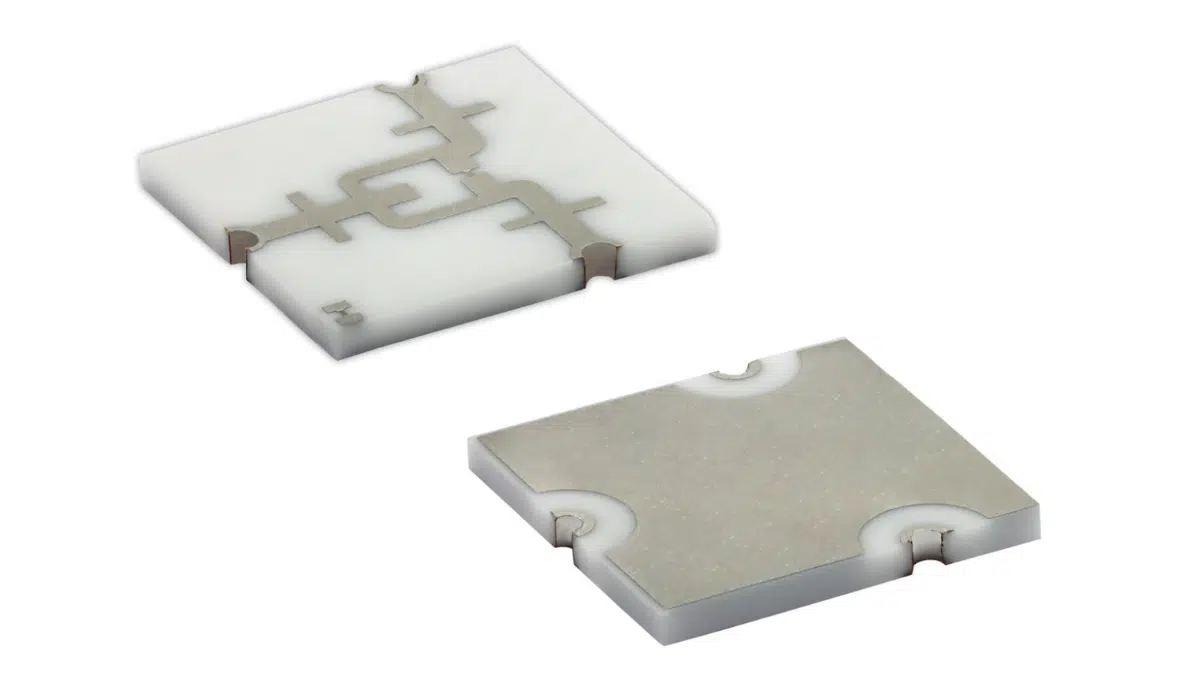
The WLKN‑000 implements a Wilkinson 2‑way divider / combiner in a compact 1817 surface‑mount package. In this topology, quarter‑wave transmission lines and isolation resistors provide:

  • Matched ports at all three connections when properly terminated.
  • Low insertion loss when ports are matched.
  • High isolation between output ports, improving channel separation.

Using thin film technology, Vishay can tightly control line impedances and resistor values, supporting broadband operation over 15 GHz to 20 GHz with consistent production behavior.

RF performance in practice

RF MetricWhat It Means in Practice
Insertion loss < 0.5 dB (below 19 GHz)Minimal impact on transmitter EIRP or receiver noise figure.
Return loss 10–15 dBControlled mismatch; acceptable for many microwave front ends.
Output isolation < 20 dB (center)Reduced crosstalk between channels, improved linearity and robustness.

In practical RF chains, these parameters help designers:

  • Maintain signal integrity in multi‑channel arrays.
  • Limit undesired coupling between parallel amplifiers or antenna branches.
  • Reduce the risk that mismatch on one branch destabilizes another when combining.

Environmental and customization aspects

  • The −55 °C to +155 °C range makes the device suitable for harsh automotive, defense, aerospace, and industrial environments.
  • The part is RoHS‑compliant, halogen‑free, Vishay Green, addressing environmental and regulatory requirements.
  • Vishay can customize the device for specific frequency bands, target return loss and insertion loss, and case sizes, which is useful when a design needs an optimized solution for non‑standard bands.
  • HFSS‑encrypted models support detailed electromagnetic simulation and co‑design with the PCB and surrounding RF structures.

Design‑in notes for engineers

When designing in the WLKN‑000, consider the following practical points.

Impedance environment and layout

  • Keep all ports at the specified system impedance (typically 50 Ω) using controlled‑impedance microstrip or coplanar waveguide on RF‑grade laminates.
  • Place the component as close as possible to the amplifier, mixer, or antenna feed to minimize interconnect loss at 15–20 GHz.
  • Follow Vishay’s recommended land pattern and solder mask openings from the datasheet to avoid parasitics that can degrade isolation and return loss.

Thermal and power considerations

  • Although insertion loss is low, at high RF power levels even small losses can result in non‑negligible dissipation. Verify junction and case temperatures against the −55 °C to +155 °C rating.
  • Pay attention to the PCB’s thermal path (copper area, via stitching) beneath and around the 1817 package, especially in high‑duty‑cycle transmitters.

System‑level RF performance

  • Use the HFSS‑encrypted models and S‑parameter data from Vishay to perform circuit and EM co‑simulation of the complete RF chain, including connectors, filters, and antennas.
  • For phased‑array and multi‑channel systems, verify that the amplitude and phase balance of the divider / combiner meet beamforming requirements across the full 15–20 GHz band.
  • Check isolation against system‑level specifications for channel‑to‑channel leakage, intermodulation, and spurious emissions.

Reliability and qualification

  • The extended temperature range and Vishay’s reputation in defense and aerospace markets make the WLKN‑000 a candidate for long‑lifecycle platforms.
  • For space or high‑reliability defense use, confirm screening options and any application‑specific qualification or derating practices via the manufacturer’s technical support channels.

Source

This article is based on information from Vishay Intertechnology’s official press release announcing the WLKN‑000 2‑way Wilkinson divider / combiner and related material available on the manufacturer’s website.

References

  1. Vishay press release – WLKN 2‑Way Wilkinson Divider / Combiner
  2. Vishay product page – WLKN

Related

Recent Posts

Vishay Introduced Thin Film Submount Platform for Optical and RF Modules

30.4.2026
32

Exxelia Releases Updated Microwave Materials and Frequency Tuning Catalogues

8.4.2026
22

Modelithics Expands COMPLETE+3D Library for Ansys HFSS

27.3.2026
13

Samtec ANSI/VITA 90 Connectors: Rugged Small Form Factor Standard

5.3.2026
41

KYOCERA AVX Extends Ultra‑Broadband RF Capacitor Series

24.2.2026
63

Bourns Extends Multilayer Chip Inductors Offer for RF and Wireless Designs

20.2.2026
28

Bourns Releases High‑Q Air Coil Inductors for RF Aplications

29.1.2026
64

Modelithics Releases Component Model Library for SIMULIA CST Studio Suite

27.1.2026
98

Modelithics COMPLETE Library v25.8 for Keysight ADS

7.1.2026
118

Upcoming Events

May 13
17:00 - 17:30 CEST

Winding Loss Modeling for Toroidal Magnetics – Including Gapped Cores

May 19
16:00 - 17:00 CEST

Designing Qi2 Wireless Power Systems: Practical Development and EMC Optimization

Jun 2
16:00 - 17:00 CEST

Calculation, Simulation and Measurement of 800V EMC Filters

View Calendar

Popular Posts

  • Buck Converter Design and Calculation

    0 shares
    Share 0 Tweet 0
  • Boost Converter Design and Calculation

    0 shares
    Share 0 Tweet 0
  • Flyback Converter Design and Calculation

    0 shares
    Share 0 Tweet 0
  • LLC Resonant Converter Design and Calculation

    0 shares
    Share 0 Tweet 0
  • MLCC and Ceramic Capacitors

    0 shares
    Share 0 Tweet 0
  • Dual Active Bridge (DAB) Topology

    0 shares
    Share 0 Tweet 0
  • What Electronics Engineer Needs to Know About Passive Low Pass Filters

    0 shares
    Share 0 Tweet 0
  • Capacitor Charging and Discharging

    0 shares
    Share 0 Tweet 0
  • MLCC Case Sizes Standards Explained

    0 shares
    Share 0 Tweet 0
  • Ripple Current and its Effects on the Performance of Capacitors

    3 shares
    Share 3 Tweet 0

Newsletter Subscription


Passive Components Blog

© EPCI - Leading Passive Components Educational and Information Site

  • Home
  • Privacy Policy
  • EPCI Membership & Advertisement
  • About

No Result
View All Result
  • Home
  • Knowledge Blog
  • PCNS

© EPCI - Leading Passive Components Educational and Information Site

This website uses cookies. By continuing to use this website you are giving consent to cookies being used. Visit our Privacy and Cookie Policy.
Go to mobile version