


This article based on Knowles Precision Devices blog explains function of DC-Blocking capacitors and its selection guide.
Electronic devices power our world and allow us to communicate. In all applications requiring signal integrity and accurate power amplification, blocking capacitors are used to provide clean waveforms and correctly amplified voltages.
Key Takeaways
- DC-Blocking capacitors are essential for ensuring signal integrity in AC and RF applications.
- Common devices needing blocking capacitors include audio amplifiers and RF systems.
- These capacitors block unwanted DC voltage, preventing waveform distortion in electronic devices.
- To select the correct blocking capacitor, consider the minimum frequency you want to pass.
- MLCCs offer tailored DC-blocking solutions with low ESR and ESL for various design needs.
What Systems Rely on Stable Waveforms?
Generally, waveform systems can be broadly defined into power-related alternating current (AC) and communications-related radio frequency (RF) applications. Both employ waveforms to provide power or information. All of these devices require a blocking capacitor to ensure the waveform conforms to the desired specifications. Some standard electronic devices requiring blocking capacitors are:
- Audio amplifiers
- RF systems such as radio, broadcast television, and microwave communications devices
- Power converters and amplifiers, AC-DC, DC-AC, and DC-DC
- Communications connectors
- Sensor interfaces
- RF filters
Why are DC-Blocking Capacitors Necessary?
In AC and RF waveforms, the desire is to have the waveform highs and lows navigate around a known base voltage. Typically, this is designed to be a waveform centered around zero volts. Some designs, like audio amplifiers, require the waveform to circulate a known direct current (DC) voltage.
However, this desire to achieve a known center level can be thwarted by the unwanted injection of a DC voltage onto the line. Some sources of DC pollution may include the following:
- Power supply residual voltage
- Offset voltage generated by a device
- Biasing circuits to control voltage levels between two (or more) levels
- Electrochemical effects such as galvanic corrosion
- Faulty or imbalanced components within a system
When any of these sources are added to (or subtracted from) the desired waveform, the center voltage is shifted into a range that corrupts or prevents data processing in RF applications or alters power amplification into unusable or dangerous ranges.
How Blocking Capacitors Remove Unwanted DC Line Levels
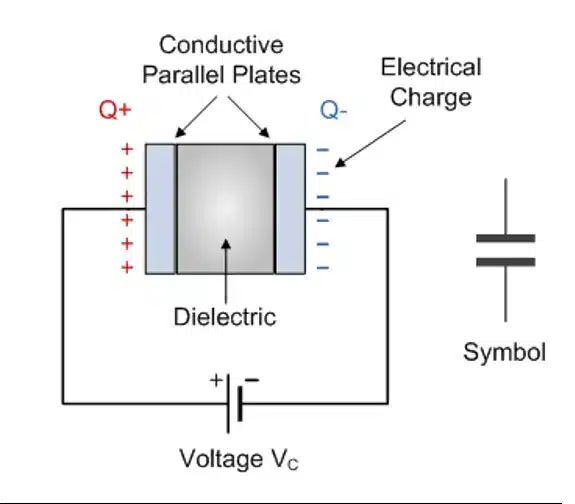
A capacitor is a passive electronic device comprised of two plates separated by a dielectric. When power is applied, the plates accumulate their respective positive and negative charge until the capacitor reaches equilibrium with the supplied voltage. See Figure 1 for capacitor physical diagram and general capacitor symbol.
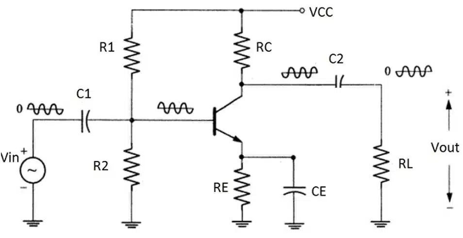
In the case of blocking capacitors, this device is placed in series with the load. Blocking an unwanted DC voltage occurs because the capacitor acts as an open to the DC voltage, not allowing it to pass through the dielectric. In Figure 2 below, capacitor C2 acts as a blocking capacitor in this voltage divider design with the output waveform around zero volts.
Any waveform on the line produces electromagnetic waves that transit the dielectric in inverse polarity to the originating wave. Thus, the DC voltage is blocked, and the wave, with a properly valued capacitor, circulates about zero volts, as desired.
In the communication world, RF signals can be transmitted over lines that require blocking capacitors to ensure the correct level is transmitted or received. For example, in coaxial lines with an inner core and outer sheath, the capacitor can be applied as an inner DC block or an outer DC block, or a capacitor can be applied as both an inner and outer DC block.
How to Select the Correct Blocking Capacitor
To better understand how a capacitor acts in a DC-blocking (otherwise known as AC-coupling) application, and how to select the correct blocking capacitor, let’s think about the behavior of an RC high pass filter circuits. In Figure 3a, you can see the RC high pass filter consists of a capacitor in series and a resistor in parallel.
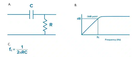
To find the 3dB frequency cutoff of this filter, you can use the formula in Figure 3b. When we plot the power that gets through this filter on a Bode plot (Figure 3c) we can see that the frequency has dropped by -3dB at the frequency cutoff we get in the formula and it drops off further at frequencies lower than the frequency cutoff, showing us how different capacitance values can attenuate low frequencies.
In practice, the above formula assumes ideal conditions. Real-world manufacturing processes introduce parasitic inductance that moves the equation to an approximation. But using this we can get a sense of the capacitance value required to pass frequencies we are interested in and to block frequencies we do not want. Any capacitance can block DC, but a designer should consider the minimum frequency they want to pass when selecting a capacitor value.
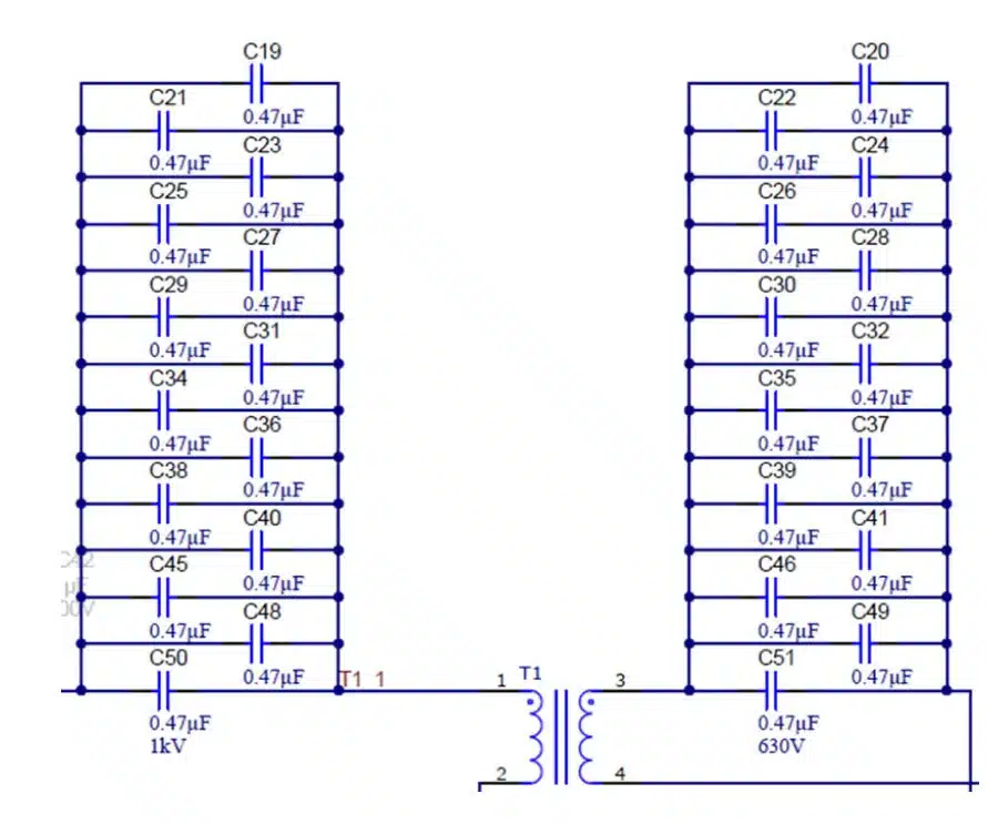
Finding blocking capacitor solutions for complex real-world electronic systems requires a deep understanding of current flows. Figure 4 below shows a blocking capacitor system added to each side of a DC-DC step-down converter used in an electronic vehicle charging device.
Multilayer ceramic capacitors (MLCCs) offer various DC-blocking solutions that can be tailored to design needs. Specific surface mount packages features very low equivalent series resistance (ESR) and equivalent series inductance (ESL).
Whether you’re designing for communications with frequencies from hertz to gigahertz, power and signal amplification systems, or ultra-sensitive sensors, MLCCs can remove unwanted DC levels from your design.
Frequently Asked Questions about DC-Blocking Capacitors
DC-blocking capacitors, also known as AC-coupling capacitors, are passive components placed in series with a circuit to prevent unwanted DC voltage from passing through, while allowing AC or RF signals to flow.
They ensure clean signal transmission by removing DC offsets that can distort waveforms, corrupt RF data, or damage amplifiers. This is critical in audio systems, RF communication, and power converters.
They are widely used in audio amplifiers, RF systems (radio, TV, microwave), power converters, communication connectors, sensor interfaces, and RF filters.
They are widely used in audio amplifiers, RF systems (radio, TV, microwave), power converters, communication connectors, sensor interfaces, and RF filters.
Selection depends on the lowest frequency you want to pass. Designers calculate the cutoff frequency of the RC high-pass filter formed by the capacitor and load resistance. MLCCs are often preferred for their low ESR and ESL in high-frequency designs.
How to Select and Use a DC-Blocking Capacitor
- Identify your application
Determine whether the capacitor will be used in audio, RF communication, or power conversion. Each application has different frequency and voltage requirements.
- Define the minimum frequency to pass
Use the RC high-pass filter formula to calculate the cutoff frequency. Ensure the capacitor value allows your desired signal frequencies to pass while blocking DC.
- Choose the capacitor type
Multilayer ceramic capacitors (MLCCs) are recommended for high-frequency and RF applications due to their low ESR and ESL. For sensitive circuits, select components with stable dielectric materials.
- Place the capacitor in series
Insert the capacitor in series with the signal path. This ensures DC is blocked while AC or RF signals are transmitted cleanly.
- Validate performance
Test the circuit with a Bode plot or simulation to confirm that the capacitor passes the desired frequency range and effectively blocks DC offsets.


