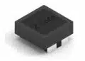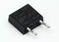










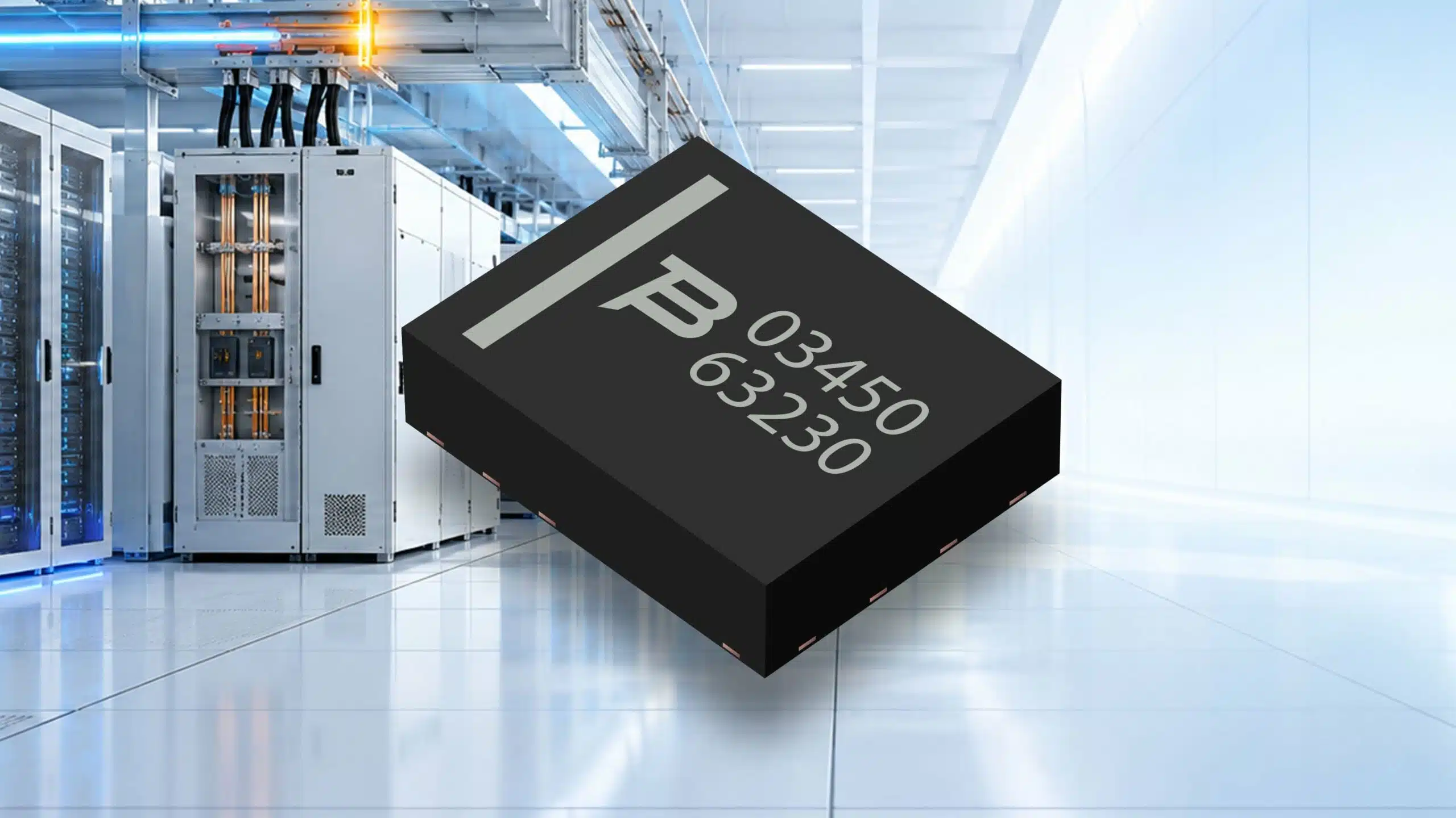
Bourns has introduced the PTVS03-450E-H, a unidirectional power transient voltage suppressor (TVS) diode for DC bus clamping.
The device combines a 450 V repetitive standoff voltage with a 300 A peak surge-current rating for an 8/20 µs waveform in a surface-mount DFN package. Target applications include DC bus protection, solid-state circuit breakers and protection within 800 VDC distribution architectures for AI deployment and racks.
Key features and benefits
- 450 V repetitive standoff voltage, with a maximum standby current of 10 µA at that voltage.
- 300 A peak surge-current capability under the IEC 61000-4-5 8/20 µs current-waveform conditions.
- Clamping voltage of 680 V at 300 A with an 8/20 µs pulse, measured at peak surge current.
- DFN package measuring 10.00 ± 0.10 mm × 8.00 ± 0.10 mm, with a height of 2.50 ± 0.10 mm.
- Operating junction temperature range of −55 °C to +150 °C.
Technical highlights
The selection of a TVS diode for transient voltage clamping requires three distinct voltage checks: normal operation below the standoff voltage, breakdown at a defined test current, and clamping under the actual surge-current conditions. These parameters are not interchangeable.
| Parameter | Value | Condition |
|---|---|---|
| Repetitive standoff voltage | 450 V | VWM |
| Breakdown voltage | 455 / 480 / 500 V | Min. / typ. / max.; 10 mA |
| Standby current | 10 µA max. | VD = 450 V |
| Peak surge current | 300 A | 8/20 µs; IEC 61000-4-5 |
| Junction temperature | −55 °C to +150 °C | Operating range |
Electrical characteristics apply at an ambient temperature of 25 °C unless otherwise noted. The 480 V typical breakdown voltage is measured at 10 mA; it is not the voltage imposed on the protected circuit while the diode carries a high-current surge.
Clamping voltage depends on current and waveform
The PTVS03-450E-H has separate clamping-voltage values for 8/20 µs and 2/10 µs pulses. At a peak current of 300 A, these are 680 V and 640 V respectively. The clamping voltage is measured at the instant of peak surge current, so the pulse waveform must remain part of any comparison or protection-margin calculation.
The 300 A rating is a transient capability tied to the 8/20 µs waveform, not a continuous-current rating. Surge-current selection must also account for ambient temperature using the device’s surge-current derating characteristic. The junction-temperature operating range does not mean that the room-temperature surge rating applies unchanged throughout that range.
Package and assembly characteristics
The molded DFN package has 100% tin terminations and a UL 94-V-0 flammability rating. Moisture sensitivity is Level 1, and the HBM ESD classification is 3B. UL agency recognition is recorded under file E215609.
The package uses a cathode band for polarity identification. PCB layout should follow the recommended footprint and cathode orientation rather than treating the package’s external dimensions as the land pattern.
Typical applications and voltage fit
- DC bus protection.
- 800 VDC distribution architectures, including AI deployment and rack protection.
- Solid-state circuit breakers.
The architecture voltage and the voltage across an individual protection component are different selection quantities. The PTVS03-450E-H remains a 450 V standoff device within an 800 VDC system. A single device must not be connected directly across a continuously energized 800 V rail; its circuit position must keep the normal voltage across it below its standoff voltage.
For a DC bus protection node, assess the maximum normal voltage across the diode first. Then compare the protected components’ voltage limits with the clamping voltage at the required pulse current and waveform. In a solid-state circuit breaker, the diode’s 300 A surge capability must not be used as the breaker’s continuous load-current rating.
Design-in notes for engineers
- Keep the highest normal voltage across the TVS below its 450 V repetitive standoff voltage.
- Check clamping voltage at the expected surge current. Do not use the 480 V typical breakdown value as the loaded clamp voltage.
- Match the required disturbance waveform to the relevant clamping and peak-current conditions; do not substitute the 2/10 µs values for an 8/20 µs event.
- Apply the surge-current derating characteristic at the intended ambient temperature.
- Minimise inductance in the surge-current connection and return. Interconnect inductance can add voltage during a surge, so assess the voltage reaching the protected circuit as well as the voltage across the TVS.
- Use the recommended PCB footprint and verify cathode orientation before layout release.
Availability and ordering
The PTVS03-450E-H is available through Bourns authorised distribution partners. Packaging is tape and reel, with 1,700 pieces per reel. The device is RoHS compliant under Directive 2015/863 and its Annex.
Further reading
- Overvoltage Protection Selection Guidelines: TVS Diodes, MOVs, and ESD MOV Varistors
- Circuit Protection Selection Guide
Source
This article is based on the Bourns product announcement and official product documentation. Engineers should refer to the current manufacturer datasheet for final design and qualification.
References
- Bourns, Bourns Introduces Model PTVS03-450E-H High-Voltage TVS Diode, 10 November 2026.
- Bourns, PTVS03-450E-H Power TVS Diode, revision October 2026.
- Bourns, Why PTVS Diodes are Optimal Solutions for User System and Power Supply Circuit Protection, July 2022.