Passive Components Blog
No Result
View All Result
  • Home
  • NewsFilter
    • All
    • Aerospace & Defence
    • Antenna
    • Applications
    • Automotive
    • Capacitors
    • Circuit Protection Devices
    • electro-mechanical news
    • Filters
    • Fuses
    • Inductors
    • Industrial
    • Integrated Passives
    • inter-connect news
    • Market & Supply Chain
    • Market Insights
    • Medical
    • Modelling and Simulation
    • New Materials & Supply
    • New Technologies
    • Non-linear Passives
    • Oscillators
    • Passive Sensors News
    • Resistors
    • RF & Microwave
    • Telecommunication
    • Weekly Digest

    Qualification of Commercial Supercapacitors for Space Applications

    Experimental Evaluation of Wear Failures in SMD Inductors

    Resonant Capacitors in High-Power Resonant Circuits

    a Schematic diagram of the BNT-based components constructed based on the entropy-increase strategy. b Digital photograph, cross-sectional SEM image, and EDS mappings of the MLCCs. c Unipolar P-E loops of MLCCs as a function of applied E. d Wrec and η of the MLCCs as a function of applied E. The comparison of (e) Wrec and η, (f) η and UF of the MLCCs with those of other recently reported state-of-the-art MLCCs. source: Nature Communications

    Researchers Proposed Enhanced Energy Storage MLCC

    Littelfuse Releases First Reflow-Compatible Illuminated Tactile Switch

    Vishay Unveils 5W Power Metal Strip Resistor in Compact 1206 Case Size

    Improving SMPS Performance with Thermal Interface Material

    Polymer Tantalum Capacitors Beyond AEC-Q200 LEO Satellites

    Components Thermal and Frequency Challenges in 6G Base Stations

    Trending Tags

    • Ripple Current
    • RF
    • Leakage Current
    • Tantalum vs Ceramic
    • Snubber
    • Low ESR
    • Feedthrough
    • Derating
    • Dielectric Constant
    • New Products
    • Market Reports
  • VideoFilter
    • All
    • Antenna videos
    • Capacitor videos
    • Circuit Protection Video
    • Filter videos
    • Fuse videos
    • Inductor videos
    • Inter-Connect Video
    • Non-linear passives videos
    • Oscillator videos
    • Passive sensors videos
    • Resistor videos

    Efficient Power Converters: Duty Cycle vs Conduction Losses

    Ripple Steering in Coupled Inductors: SEPIC Case

    SEPIC Converter with Coupled and Uncoupled Inductors

    Coupled Inductors in SEPIC versus Flyback Converters

    Non-Linear MLCC Class II Capacitor Measurements Challenges

    Percolation Phenomenon and Reliability of Molded Power Inductors in DC/DC converters

    Root Causes and Effects of DC Bias and AC in Ceramic Capacitors

    How to Calculate the Output Capacitor for a Switching Power Supply

    Switched Capacitor Converter Explained

    Trending Tags

    • Capacitors explained
    • Inductors explained
    • Resistors explained
    • Filters explained
    • Application Video Guidelines
    • EMC
    • New Products
    • Ripple Current
    • Simulation
    • Tantalum vs Ceramic
  • Knowledge Blog
  • Suppliers
    • Who is Who
  • Events
No Result
View All Result
Passive Components Blog
No Result
View All Result

Experimental Evaluation of Wear Failures in SMD Inductors

1.10.2025
Reading Time: 4 mins read
A A

The paper “Experimental Evaluation of Wear Failures in SMD Inductors” was presented by Masaaki Tsujii, Murata Manufacturing Co., Ltd., Kyoto, Japan at the 5th PCNS Passive Components Networking Symposium 9-12th September 2025, Seville, Spain as paper No. 6.2.

Introduction

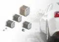
The rapid electrification of the automotive industry and the rise of autonomous driving technologies have significantly increased the operational demands placed on automotive electronic components.

RelatedPosts

Qualification of Commercial Supercapacitors for Space Applications

Resonant Capacitors in High-Power Resonant Circuits

Improving SMPS Performance with Thermal Interface Material

With vehicle lifetimes extending to 10–20 years, ensuring long-term component reliability has become critical. A key approach to this challenge is Mission Profile validation, which defines the environmental and operational conditions components will face throughout their service life.

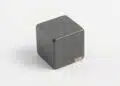
Surface-mounted device SMD inductors, such as multilayer ferrite beads, are widely used in automotive systems but have been less studied in terms of wear failure mechanisms under realistic Mission Profile conditions. This study investigates the high-temperature, high-current wear failure behavior of multilayer ferrite SMD inductors.

Key Points

  • Mission Profile assessments simulate environmental and operational stresses to predict long-term component reliability.
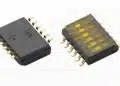
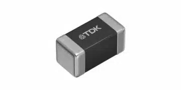
  • Multilayer ferrite beads with screen-printed Ag internal coils and Ni/Sn external electrodes were tested under high-stress conditions.
  • Experiments involved 10 A DC current at 150 °C, far exceeding the normal rated current.
  • Failures were associated with electromigration, intermetallic compound (IMC) formation, and void generation.
  • DC resistance increased after 200 hours due to IMC growth and voiding, leading toward potential thermal runaway and open failure.

Extended Summary

The study began by acknowledging the growing importance of Mission Profile-based validation in the automotive sector, emphasizing the lack of detailed data on SMD inductor wear failures. To explore these mechanisms, Murata fabricated prototype multilayer ferrite beads featuring two straight internal Ag coil layers and Ni/Sn-plated external electrodes. These inductors were mounted on evaluation boards using Sn-3.0Cu-0.5Ag solder and stressed in a 150 °C chamber with 10 A applied current to accelerate failure mechanisms.

Initial cross-sectional imaging confirmed the baseline structure of the inductors, with uniform Ni plating and intact Ag paste layers. For approximately 200 hours, the DC resistance remained stable, after which it began to rise. SEM and EDX analysis after 600 hours revealed polarity-dependent material migration: on the anode side, Cu and Sn intermetallics formed along the Ni plating, while on the cathode side, Ni plating was partially depleted, and Cu/Ni intermetallics developed in the solder outside the fillet. Voids were observed along the cathode external electrode, coinciding with regions of Ni loss.

The observed behavior was linked to electromigration, whereby electron flow drives Cu and Ni diffusion according to current polarity. Ni migration from the cathode toward the substrate land and Sn diffusion into the Ag paste layer led to the formation of high-resistivity intermetallic compounds. This progression caused the increase in DC resistance over time, and the voids further contributed to resistive growth. If allowed to continue, this process could result in localized heating, thermal runaway, and complete open failure.

The study also highlighted the significant role of Sn crystallographic orientation in Ni diffusion rates, explaining the uneven distribution of IMCs. The combined effects of IMC growth and void formation under accelerated conditions provide critical insight into the failure mechanisms of SMD inductors during long-term service in automotive applications.

Conclusion

This experimental evaluation demonstrated that under high-temperature, high-current stress, multilayer ferrite SMD inductors exhibit wear failures driven by electromigration. Key mechanisms include polarity-dependent diffusion of Cu and Ni, Ni plating depletion, Sn infiltration into the Ag paste layer, and intermetallic compound formation accompanied by voiding. The resulting increase in DC resistance signals the onset of potential thermal runaway and eventual open failure. This research lays the groundwork for developing accurate acceleration models, identifying countermeasures, and designing more robust inductors for the next generation of automotive electronics.

6_2_Murata_Experimental Evaluation of Wear Failures in SMD InductorsDownload

Related

Source: PCNS

Recent Posts

Qualification of Commercial Supercapacitors for Space Applications

1.10.2025
0

Resonant Capacitors in High-Power Resonant Circuits

1.10.2025
3
a Schematic diagram of the BNT-based components constructed based on the entropy-increase strategy. b Digital photograph, cross-sectional SEM image, and EDS mappings of the MLCCs. c Unipolar P-E loops of MLCCs as a function of applied E. d Wrec and η of the MLCCs as a function of applied E. The comparison of (e) Wrec and η, (f) η and UF of the MLCCs with those of other recently reported state-of-the-art MLCCs. source: Nature Communications

Researchers Proposed Enhanced Energy Storage MLCC

1.10.2025
2

Littelfuse Releases First Reflow-Compatible Illuminated Tactile Switch

1.10.2025
1

Vishay Unveils 5W Power Metal Strip Resistor in Compact 1206 Case Size

1.10.2025
2

Improving SMPS Performance with Thermal Interface Material

30.9.2025
5

Polymer Tantalum Capacitors Beyond AEC-Q200 LEO Satellites

30.9.2025
16

Components Thermal and Frequency Challenges in 6G Base Stations

30.9.2025
8

Development of Nitrogen-Doped Graphene Supercapacitors 

30.9.2025
6

Layer-by-Layer Fabrication of Thin Polypropylene-based Dielectrics

30.9.2025
18

Upcoming Events

Sep 30
September 30 @ 12:00 - October 2 @ 14:00 EDT

MIL-Std-883 TM 2010

Oct 8
11:00 - 12:00 CEST

PCB Online Shop – simply “Made in Germany” by Würth Elektronik

Oct 14
16:00 - 17:00 CEST

Smart Sensors, Smarter AI: Building Reliable Edge Systems

Oct 17
12:00 - 14:00 EDT

External Visual Inspection per MIL-STD-883 TM 2009

Oct 20
October 20 - October 23

Digital WE Days 2025 – Virtual Conference

View Calendar

Popular Posts

  • Buck Converter Design and Calculation

    0 shares
    Share 0 Tweet 0
  • Boost Converter Design and Calculation

    0 shares
    Share 0 Tweet 0
  • Flyback Converter Design and Calculation

    0 shares
    Share 0 Tweet 0
  • LLC Resonant Converter Design and Calculation

    0 shares
    Share 0 Tweet 0
  • Dual Active Bridge (DAB) Topology Explained

    0 shares
    Share 0 Tweet 0
  • SEPIC Converter Design and Calculation

    0 shares
    Share 0 Tweet 0
  • What is a Dielectric Constant and DF of Plastic Materials?

    4 shares
    Share 4 Tweet 0
  • Ripple Current and its Effects on the Performance of Capacitors

    3 shares
    Share 3 Tweet 0
  • MLCC and Ceramic Capacitors

    0 shares
    Share 0 Tweet 0
  • Flying Capacitors Explained

    0 shares
    Share 0 Tweet 0

Newsletter Subscription


Passive Components Blog

© EPCI - Leading Passive Components Educational and Information Site

  • Home
  • Privacy Policy
  • EPCI Membership & Advertisement
  • About

No Result
View All Result
  • Home
  • Knowledge Blog
  • Premium Suppliers

© EPCI - Leading Passive Components Educational and Information Site

This website uses cookies. By continuing to use this website you are giving consent to cookies being used. Visit our Privacy and Cookie Policy.
Go to mobile version