Passive Components Blog
No Result
View All Result
  • Home
  • NewsFilter
    • All
    • Aerospace & Defence
    • Antenna
    • Applications
    • Automotive
    • Capacitors
    • Circuit Protection Devices
    • electro-mechanical news
    • Filters
    • Fuses
    • Inductors
    • Industrial
    • Integrated Passives
    • inter-connect news
    • Market & Supply Chain
    • Market Insights
    • Medical
    • Modelling and Simulation
    • New Materials & Supply
    • New Technologies
    • Non-linear Passives
    • Oscillators
    • Passive Sensors News
    • Resistors
    • RF & Microwave
    • Telecommunication
    • Weekly Digest

    How to Manage Supercapacitors Leakage Current and Self Discharge 

    Qualification of Commercial Supercapacitors for Space Applications

    Experimental Evaluation of Wear Failures in SMD Inductors

    Resonant Capacitors in High-Power Resonant Circuits

    a Schematic diagram of the BNT-based components constructed based on the entropy-increase strategy. b Digital photograph, cross-sectional SEM image, and EDS mappings of the MLCCs. c Unipolar P-E loops of MLCCs as a function of applied E. d Wrec and η of the MLCCs as a function of applied E. The comparison of (e) Wrec and η, (f) η and UF of the MLCCs with those of other recently reported state-of-the-art MLCCs. source: Nature Communications

    Researchers Proposed Enhanced Energy Storage MLCC

    Littelfuse Releases First Reflow-Compatible Illuminated Tactile Switch

    Vishay Unveils 5W Power Metal Strip Resistor in Compact 1206 Case Size

    Improving SMPS Performance with Thermal Interface Material

    Polymer Tantalum Capacitors Beyond AEC-Q200 LEO Satellites

    Trending Tags

    • Ripple Current
    • RF
    • Leakage Current
    • Tantalum vs Ceramic
    • Snubber
    • Low ESR
    • Feedthrough
    • Derating
    • Dielectric Constant
    • New Products
    • Market Reports
  • VideoFilter
    • All
    • Antenna videos
    • Capacitor videos
    • Circuit Protection Video
    • Filter videos
    • Fuse videos
    • Inductor videos
    • Inter-Connect Video
    • Non-linear passives videos
    • Oscillator videos
    • Passive sensors videos
    • Resistor videos

    Efficient Power Converters: Duty Cycle vs Conduction Losses

    Ripple Steering in Coupled Inductors: SEPIC Case

    SEPIC Converter with Coupled and Uncoupled Inductors

    Coupled Inductors in SEPIC versus Flyback Converters

    Non-Linear MLCC Class II Capacitor Measurements Challenges

    Percolation Phenomenon and Reliability of Molded Power Inductors in DC/DC converters

    Root Causes and Effects of DC Bias and AC in Ceramic Capacitors

    How to Calculate the Output Capacitor for a Switching Power Supply

    Switched Capacitor Converter Explained

    Trending Tags

    • Capacitors explained
    • Inductors explained
    • Resistors explained
    • Filters explained
    • Application Video Guidelines
    • EMC
    • New Products
    • Ripple Current
    • Simulation
    • Tantalum vs Ceramic
  • Knowledge Blog
  • Suppliers
    • Who is Who
  • Events
No Result
View All Result
Passive Components Blog
No Result
View All Result

Hirose Releases High Current Vibration-Resistant Connectors

4.8.2025
Reading Time: 2 mins read
A A

Hirose Electric unveils industry leading high current vibration-resistant connectors for the EV and HEV Markets.

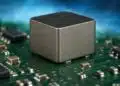
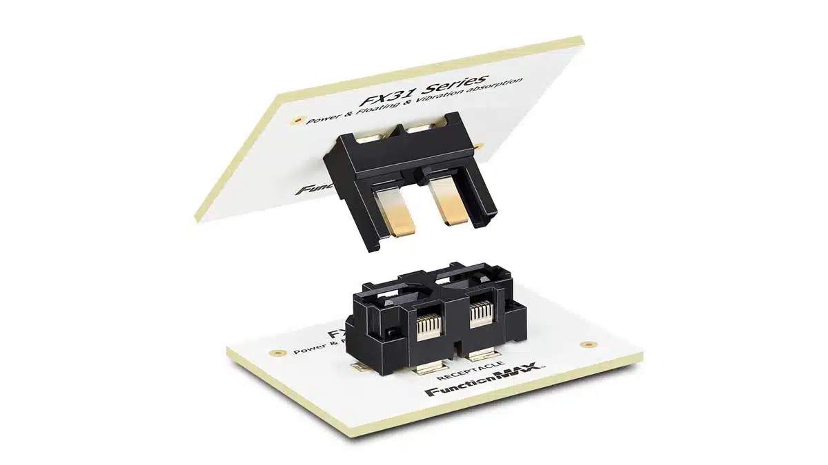
Hirose Electric Co., Ltd. announced the launch of the FX31 Series, the world’s first board-to-board connector series that combines high current capability with a rugged, vibration-resistant design.

RelatedPosts

Hirose Launches World’s Lowest Profile and Narrowest Pitch FPC Connector

Hirose Unveils Compact Waterproof Version of IEC-Compliant ix Industrial Connector

Hirose Introduces One Action Top and Bottom Contact Connectors

This groundbreaking innovation is set to transform the automotive industry by addressing the growing demands of electric vehicles (EVs) and hybrid electric vehicles (HEVs) for high currents and durability in harsh vibration environments.

Powertrain Innovation: Unlocking New Possibilities with High-Current Connectors

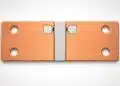
As powertrain systems in EVs and HEVs increasingly require high currents, traditional busbars with screw-fastening methods have posed challenges such as large component size, limited design flexibility, and complex assembly. Hirose Electric has leveraged its expertise in vibration-resistant signal connectors to develop the FX31, a connector-based solution that replaces conventional busbars. This innovation enables miniaturization, weight reduction, and supports assembly automation, leading to greater manufacturing efficiency and cost savings.

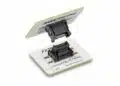
The FX31, when combined with the FX26 Series for signal transmission, supports hybrid power and signal connections in a compact form factor, contributing to high-density mounting and significant cost reductions.

Unique Features of the FX31 Series

  • World’s First High Current + Vibration-Resistant Structure: The FX31 features a proprietary floating design that absorbs vibration and shock while safely delivering high current, up to 25A per contact, with potential support for up to 40A per contact in a 2-position configuration.
  • Floating Design for Greater Assembly Flexibility and Labor Savings: Eliminates the need for screw fastening, facilitating seamless integration into automated assembly lines, including robotic systems.
  • Compact and Lightweight: Smaller and lighter than traditional busbars, offering greater design flexibility for PCB layouts.
  • Hybrid Connection with FX26 Series: Supports high-density mounting and contributes to total cost reduction when combined with the FX26 Series for signal lines.

The FX31 Series is designed to support powertrain system integration and meet the high-current demands of next-generation high-end IVI (In-Vehicle Infotainment) automotive computers, driving continued market expansion.

Under Development

Hirose Electric is expanding the FX31 Series lineup to meet customer demand, with the following variations currently in mass production and planned for development:

  • Currently in Mass Production: 2-position connectors with a height of 20mm.
  • Planned for Development: 3-position and 4-position connectors with heights of 25mm and 30mm, respectively.

Related

Source: Hirose

Recent Posts

How to Manage Supercapacitors Leakage Current and Self Discharge 

1.10.2025
8

Experimental Evaluation of Wear Failures in SMD Inductors

1.10.2025
9

Resonant Capacitors in High-Power Resonant Circuits

1.10.2025
7

Vishay Unveils 5W Power Metal Strip Resistor in Compact 1206 Case Size

1.10.2025
6

Polymer Tantalum Capacitors Beyond AEC-Q200 LEO Satellites

30.9.2025
26

Flaked Tantalum Powders: High Capacitance Powders for High Reliable Tantalum Capacitors

29.9.2025
13

Design of High Precision Integrated Resistive Voltage Dividers

29.9.2025
13

Samsung Electro-Mechanics Releases 470nF 16V MLCC in 0402 Size

29.9.2025
12

Advancements in Flexible End Terminations for Robust MLCCs in EV

26.9.2025
27

Lifetime Assessment for Capacitors in EPS Application

25.9.2025
39

Upcoming Events

Sep 30
September 30 @ 12:00 - October 2 @ 14:00 EDT

MIL-Std-883 TM 2010

Oct 8
11:00 - 12:00 CEST

PCB Online Shop – simply “Made in Germany” by Würth Elektronik

Oct 14
16:00 - 17:00 CEST

Smart Sensors, Smarter AI: Building Reliable Edge Systems

Oct 17
12:00 - 14:00 EDT

External Visual Inspection per MIL-STD-883 TM 2009

Oct 20
October 20 - October 23

Digital WE Days 2025 – Virtual Conference

View Calendar

Popular Posts

  • Buck Converter Design and Calculation

    0 shares
    Share 0 Tweet 0
  • Boost Converter Design and Calculation

    0 shares
    Share 0 Tweet 0
  • Flyback Converter Design and Calculation

    0 shares
    Share 0 Tweet 0
  • LLC Resonant Converter Design and Calculation

    0 shares
    Share 0 Tweet 0
  • Dual Active Bridge (DAB) Topology Explained

    0 shares
    Share 0 Tweet 0
  • SEPIC Converter Design and Calculation

    0 shares
    Share 0 Tweet 0
  • What is a Dielectric Constant and DF of Plastic Materials?

    4 shares
    Share 4 Tweet 0
  • Ripple Current and its Effects on the Performance of Capacitors

    3 shares
    Share 3 Tweet 0
  • MLCC and Ceramic Capacitors

    0 shares
    Share 0 Tweet 0
  • Flying Capacitors Explained

    0 shares
    Share 0 Tweet 0

Newsletter Subscription


Passive Components Blog

© EPCI - Leading Passive Components Educational and Information Site

  • Home
  • Privacy Policy
  • EPCI Membership & Advertisement
  • About

No Result
View All Result
  • Home
  • Knowledge Blog
  • Premium Suppliers

© EPCI - Leading Passive Components Educational and Information Site

This website uses cookies. By continuing to use this website you are giving consent to cookies being used. Visit our Privacy and Cookie Policy.
Go to mobile version