


Wirewound resistors are type of passive components in which metal wires are used to reduce or restrict the flow of electric current to a certain level.
Key Takeaways
- Wirewound resistors consist of metal wires that control electric current, categorized mainly into power and precision types.
- Power wirewound resistors manage high temperatures for high power applications, while precision wirewound resistors ensure high accuracy at low temperatures.
- Other considerations include tolerances, temperature coefficients, and the risk of inductance at high frequencies affecting performance.
- Applications range from telecommunications to medical devices, emphasizing their versatility in electronic circuits.
- Specific designs and protective encapsulations influence performance, with different materials used for insulation and thermal management.
Wirewound Resistor Types
The basic two types of wirewound resistors are: power wirewound resistors and precision wirewound resistors.
Power wirewound resistor. This is a non-inductive wirewound resistor that operates at high temperature. It is commonly used for high power applications.
Precision wirewound resistor. This operates at low temperature with high accuracy. It is used as a precision resistor in instrumentation because of its high accuracy.
Available tolerances and temperature coefficients vary; devices designed for precision with sub-0.1% tolerance and temperature coefficients in the tens of PPM/°C are available, though the plurality of available devices at the time of writing are specified nearer to 1% tolerance and 200PPM/°C or less.
Wirewound resistors are used only for low frequencies, and are not suitable for high frequencies. At high frequencies, these act as inductors. Hence, for high frequencies, non-inductive wirewound resistors are used.
Wirewound resistors find use in almost all major electronic circuits, and are widely used in applications such as telecommunications, computers, audio and video equipment, medical electronic equipment, defence and space, telephone switching systems, transducers instrumentation, current and voltage balancing, and current sensing.
General Comments
As the name indicates wirewound resistors consist of a resistive wire wound on a bobbin and supplied with a protective coating. Since the resistance wire never can serve as a termination wire because of solderability requirements, it has to be connected to the terminal leads or the like, usually by welding or brazing.
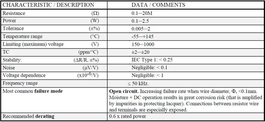
The higher the resistance value the thinner the wire that has to be used and thus the greater the risk of open circuits due to deficient weldings, damage from corrosion or from mechanical handling. Below a diameter, Φ, of 0.1 mm (4 mils) the failure rate grows rapidly.
Of course, the winding is inductive which might be troublesome at frequencies above 50 kHz. There exist low inductance winding styles but price and dimensions then will increase. They are used for precision wirewound designs.
The simplest solution is by using sections of winding, with inverse winding direction from section to section, thus causing the magnetic fields to counteract each other. Less inductive will be the double-wound winding, where the wire is folded on the middle to a “double-wire” that is wound on the core. The drawback is its capacitive connection between the wire halves. This capacitive connection may be eliminated by the so called Ayrton-Perry-winding where two wires are wound in opposite directions on the core and then connected in parallel. The drawback is the increased wire volume. See Figure 2. below.
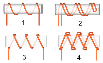
Types of windings in wire resistors:
- common
- bifilar double-wound
- common on a thin former
- Ayrton–Perry
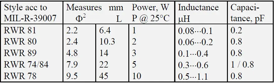
Examples of inductance in power resistors of the same design as indicated in Figure 1. are shown in Table 1. that also contain information about their capacitance. Capacitance is always developed between adjacent turns and manifests itself at higher frequencies.
Power Wirewound Resistors
Introduction
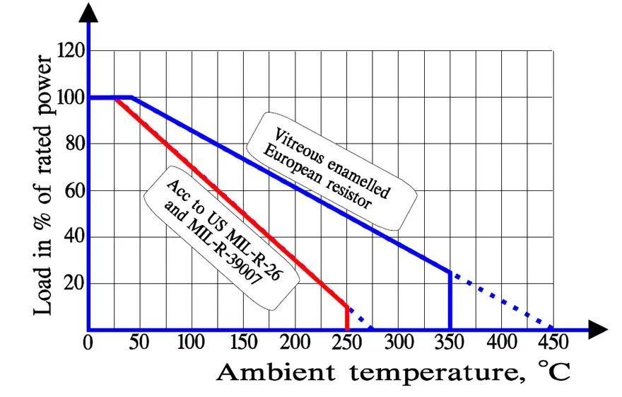
This type of resistors is, as the name indicates, designed to dissipate power. That means comparatively high operation temperatures and a limited stability, which in turn influences the tolerance settings. The break point of the power curve is usually situated at 25 °C. The derated part of the curve often aims at zero power at ambient temperatures like 275, 350 or even 450 °C but has a second break point at 250 or 350 °C as shown in Figure 3. Other characteristic curves don’t have the second break point. They are derated linearly to zero power and reach zero applied power at, for example, 200, 275 or even 350 °C.
The high Hot Spot temperatures of power resistors demand particular attention during mounting. Otherwise, adjacent parts may be damaged by the heat. When solder connections are used it is important to ensure that the temperature in the solder joints does not come near to the melting point of the solder.
The high operating temperatures require bobbins of a heat resistant material. Porcelain, alumina, beryllia and glass fiber cores are used. The higher the thermal conductivity, the better. The Hot Spot curve then is flattened and widened to a corresponding degree. Beryllium oxide – beryllia – is the best but that material is controversial due to it’s high toxicity in the gaseous or powder state. It is the author’s firm and well-founded opinion that risk of poisoning is possible only when dry grinding during DPA or in the extremely rare occasion of an electric arc that may hit enameled resistors. See Caution below. Moreover, beryllium oxide resistors normally are lacquered, not enameled.
There are four main types of cover/encapsulation:
- vitreous enamel
- cement
- silicon lacquer/plastic molding
- finned aluminum housed.
Pulse Loads
Wirewound power resistors can stand considerable pulse loads. The following outlines apply:
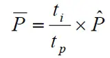
- With reference to resistors pulse load article , P– should be limited to PR at periodic pulse loads. We get the connection between from
- Singular pulses must not exceed Vg2/R.
For a decreasing resistance, R, the generated power, Vg2/R, may rise beyond permissible values. We may have to set bounds for the allowable pulse load or the pulse time or both. The following calculations can be of help by determining the conditions.
By means of the thermal resistance Rth we can calculate the Hot Spot temperature Thsp as Rth x Ppulse. If we then calculate with a constant power Ppulse this power will raise the surface temperature to T∞ in Figure 3. When the corresponding curve passes TR we get the time tp. If the power is switched off after the time tp the temperature development certainly will get an overshoot before it turns down again. But the resistor can stand a certain over-temperature; partly the Thsp is calculated on the nominal Rth and this value is higher than the real Rth according to Figure 5. Altogether, this will compensate for reasonably hazardous temperatures.
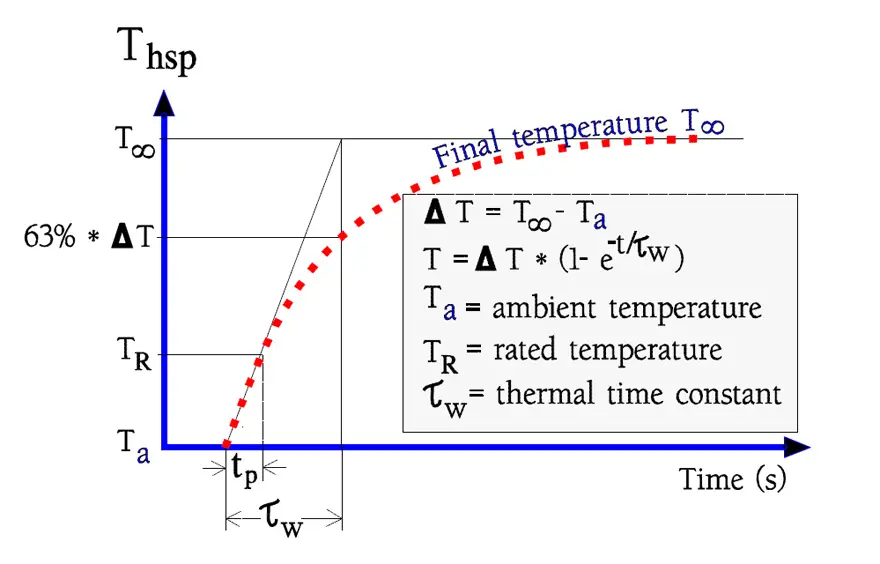
The curve in Figure 3. is drawn by means of T∞ and τw which are supposed to be constant in these estimates. If the pulse time is longer than the one in Figure 3., for example 2 tp, we then have to construct another curve through the co-ordinates (2 tp; TR) and reduce the pulse load in correspondence to the decreased T∞.
Vitreous enameled
Vitreous enamel offers an excellent protection for power resistors. The quality, however, may vary. The enamel should be well adherent and free of pores and without any impurities. Quality assurance is necessary to achieve this level of quality.
The high manufacturing temperature of approximately 800 °C brings with it certain problems. At that high temperatures the wire stretches. Since it is wound with a moderate tensional bias it happens on geometrically large bodys that some turns stick together in a spot because of the capillary forces. Normally the phenomenon is visible only by means of X-ray. It looks like turns leaning against each other. It has not been proved that this contact leads to flash-overs between turns or any other troubles (Figure 4.).
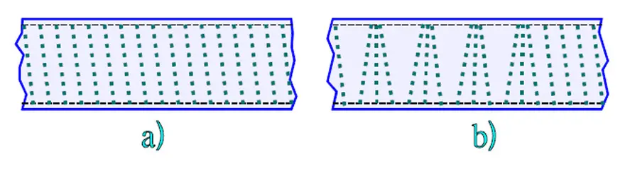
a) in a normal state; b) with “stick-together” resulting from the enameling.
More troublesome is that the high manufacturing temperature makes it difficult to use solderable wire alloys of copper- nickel, both for the resistor elements and the terminal leads. The latter are tinned after the enameling process but the solderability still is deteriorated compared to that of Cu-Ni alloys.
Bigger power resistors often are manufactured with terminals of bands, lugs, shells or end caps that are soldered, squeezed or fastened with screws to the corresponding terminals on the apparatus.
Caution! If the resistor should be subjected to an unintentional strong over-load the enamel may attain its melting temperature before the wire burns off. Then the vitreous enamel will become conducting and will short-circuit the resistor. If the main circuit has low impedance and is of power type an electric arc is developed that lasts until the fuse cuts off.
Cemented
Cement is a common protection material but provides in reality only touch protection. Generally the moisture protection is poor but there are exceptions in the market.
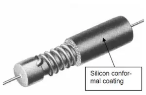
Lacquered / Plastic molded
Better than cement are lacquered or plastic molded resistors. Most often the lacquer is of a silicon basis. These encapsulations are not affected by the high manufacturing temperatures of the vitreous enamel and thus the resistors can be supplied with terminal leads of more solderable alloys.
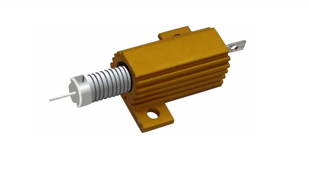
Aluminum housed, chassis mount
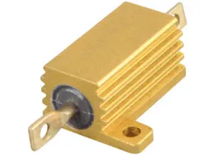
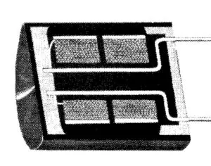
If we supply the resistor with a finned aluminum housing as shown in Figure 5., the Hot Spot temperature is lowered and the temperature better distributed over the length of the resistor body, which in turn permits a stronger load for a specific bobbin size.
Note! The power information of the data sheets concerning this type of resistor applies only if the resistor is mounted on the specified heat sink plates.
Adjustable
A quite specific type of fixed resistors are the so-called adjustable ones. See the example in Figure 6.
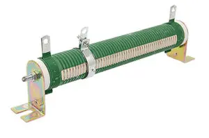
If possible, use of these should be avoided. The reasons are several. The resistive wire has to be made by alloys that don’t oxidize too easily. The adjustment implies touch contact in the open window. Thus the wire will be more disposed to corrosion than that of a conventional design. The open contact window without any corrosion or touch protection doesn’t make it any better. Finally the actual adjustment procedure is risky. It is very easy to slip with the screwdriver and damage the wire. Below a diameter, F, of 0.2 mm (8 mils) the failure rate starts increasing rapidly. Compared to other power types the adjustable have a 50……100 times greater failure rate.
Low ohmic design
In the range from 5 to 800 mΩ so called “low-ohmic” value resistors are offered. The resistance element consists in principle of a straight wire or band to which the terminal leads are welded. As a rule these resistors are encapsulated.
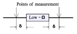
In the low ohmic range the TC of the terminal leads play a greater and greater part. Their own TC usually is strongly positive – for example, copper has + 3900 ppm/°C – and the lower the resistance value, the more the resistance and TC of the terminal leads influence.
Please remember that the tolerance requirements apply only when we connect according to the manufacturer’s instructions, i.e., at a specified distance from the component body (Figure 7.).
Precision Wirewound Resistors
Precision wirewound resistors are characterized by close tolerances, high resistance stability, moderate power ratings/Hot Spot temperatures and close TCRs. Typical values of these characteristics are shown in the following Table 2.
Introduction
More and more precision wirewound resistors are being displaced with metal film types which have the same characteristics but considerably smaller dimensions. In older designs, however, they still exist and therefore we will deal with this component type.
In the simplest construction the wire is wound in several layers, something like a spool of thread. Short-circuiting between turns normally is prevented by the polyamide lacquer but there have been occasions when the wire tension during winding has become too great. The polyamide “flows” away and turns have been short-circuited thus resulting in a resistance decrease – in certain cases, intermittently.
In more expensive designs the winding is divided in sections – Figure 8. – and the winding direction is veered round in order to reduce the inductance.
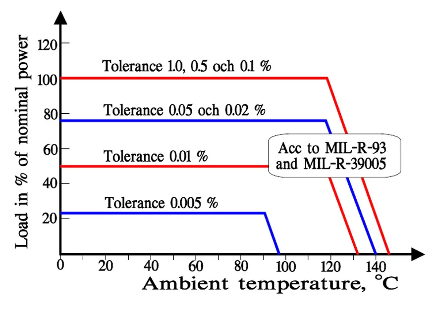
The resistors usually are encapsulated in a plastic molding. However, the liquid plastic may after-cure and the bobbin may change its dimensions. This will inevitably lead to change in wire tension and a subsequent resistance change. The wire tension is crucial and is held as low as possible during winding. In order to prevent resistance changes during operation such changes are released in advance by artificial aging of the whole construction at 170…200 °C. That temperature must not be exceeded in the application. The lower operating temperature, the better stability. Thus the derating is in direct proportion to the fineness of the tolerances. Figure 9. shows examples from older editions of US military specifications on the connection between tolerance and derating.
The manufactured temperature coefficient is, like the tolerance, related to the stability. By tradition, wirewound designs have had an advantage over the metal film. It has been easier manufacturing a thoroughly checked alloy with specific TC characteristics in a wire than in a metal film. However, in recent years that difference has shrunk and in certain cases been eliminated.
Linear PTC designs
Another branch where wire previously has dominated is PTC designs. The pure metals have a greatly positive TC, between 3000 and 6000 ppm/ °C, and accordingly this has been utilized. The TC characteristic is never completely straight but swings off, more or less. If we on the other hand compare with thermistors the TC curve is “straight”. Everything is relative. Since the resistivity for pure metals is low compared to traditional resistance wires the resistance range will be greatly limited on higher values.
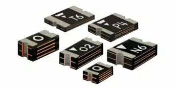
SMD Wirewound Resistors
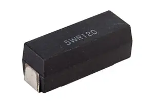
Resistor chips in wirewound design are not common. There are precision designs for SMD but they actually consist of molded variants where the axial terminal leads have been bent to a so called gull-wing shape or the like. SMD types for high power single pulse resistors also exist. A typical appearance of a molded surface mount 5W wirewound resistor is shown in Figure 10.
Summary Tables
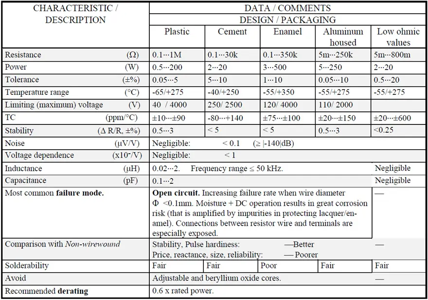
Behind the headings resistance, power, tolerance and TC manufactured maximum and minimum values from the more serious suppliers are shown. Even if extremes have been excluded as far as possible, the content in the tables should not be regarded as recommended manufacturing ranges. Moreover, one manufacturer may cover the upper part of the range, another the lower part. Recommended manufacture ranges are found in the so called QPLs – qualified product lists – and they usually have a more limited extension except for one important consideration: stability. There, respective standards show maximum limits for changes and they usually are higher than the manufacturer’s catalogue data that sooner show typical changes. Stability data in the tables are based on information from standards. Since the standards contain different degrees of severity we can’t get any unequivocal stability information but a range.
The general derating that is recommended is based on the author’s experience and analysis of relevant information within the subject field. One source of information ought to be mentioned: MIL-HDBK-979. More severe environments and important applications may justify a harder derating.
Conclusion
Wirewound resistors remain essential passive components for demanding applications requiring high power dissipation, pulse handling, and reliability. Their robust construction using resistive wire wound on insulating cores enables superior performance in power circuits, precision instrumentation, and harsh environments, despite challenges like inherent inductance and larger sizes.
Key Strengths
Power variants excel in high-temperature operation and pulse loads up to Vg2/R, with derating curves ensuring safe use up to 450°C ambient. Precision types offer tight tolerances (<0.1%) and low TCRs (tens of ppm/°C), ideal for stable measurements.
Limitations
Inductive behavior limits high-frequency use (>50 kHz), mitigated by Ayrton-Perry or bifilar windings, though increasing size and cost. Encapsulations like vitreous enamel provide protection but demand careful mounting to avoid heat damage.
Applications
Widely deployed in telecommunications, EVs, defense, and current sensing, where metal film alternatives fall short on power or surge needs. Summary tables highlight ranges: power types up to high ohms with 1-5% tolerance; precision down to sub-ppm stability.
FAQ
Wirewound resistors are passive components in which metal resistance wires are wound on insulating bobbins to restrict electric current flow. They consist of resistive wire wound on heat-resistant cores like porcelain, alumina, or glass fiber, protected by vitreous enamel, cement, silicon lacquer, or aluminum housings.
The two basic types are power wirewound resistors and precision wirewound resistors. Power types operate at high temperatures for high-power applications, while precision types operate at low temperatures with high accuracy (sub-0.1% tolerance and temperature coefficients in tens of PPM/°C) for instrumentation use.
Wirewound resistors are widely used in telecommunications, computers, audio/video equipment, medical electronics, defense and space systems, telephone switching, transducers, instrumentation, current and voltage balancing, and current sensing applications. Electric vehicles and power circuits particularly benefit from their pulse handling capabilities
Key advantages include high power dissipation capacity, excellent pulse load handling (up to Vg²/R for singular pulses), superior temperature stability, tight tolerances available (<0.1%), low temperature coefficients (tens of PPM/°C for precision types), and reliable operation in harsh environments up to 450°C ambient.
Main limitations include inherent inductance making them unsuitable above 50 kHz frequencies, larger physical dimensions compared to film resistors, higher cost especially for low-inductance designs (Ayrton-Perry or bifilar windings), and potential risks with adjustable types which have 50-100 times greater failure rates.
How to Select the Right Wirewound Resistor Type
- Determine power dissipation requirements
Calculate the maximum power your circuit will dissipate and ambient temperature conditions. Power wirewound resistors handle high wattages with derating curves extending to 275-450°C ambient, while precision types prioritize stability over power capacity.
- Assess frequency and inductance needs
For frequencies below 50 kHz, standard wirewound resistors work well. Above 50 kHz, specify low-inductance designs using bifilar (double-wound) or Ayrton-Perry windings to counteract magnetic fields, though these increase size and cost.
- Evaluate pulse load conditions
For periodic pulse loads, limit peak power to rated power PR using the relationship from derating curves. Singular pulses must not exceed Vg²/R to prevent wire damage or enamel melting in vitreous enameled types.
- Select appropriate encapsulation
Choose vitreous enamel for maximum protection (though it may short-circuit under extreme overload), cement for basic touch protection, silicon lacquer/plastic molding for better moisture resistance and solderable terminals, or finned aluminum housings for improved heat distribution and higher power ratings.
- Verify tolerance and temperature coefficient specifications
Match tolerance (1-5% for power types, <0.1% for precision) and TCR (200 PPM/°C for power, tens of PPM/°C for precision) to your application accuracy requirements. Remember that tighter tolerances require more aggressive derating per MIL specifications.


