Passive Components Blog
No Result
View All Result
  • Home
  • NewsFilter
    • All
    • Aerospace & Defence
    • Antenna
    • Applications
    • Automotive
    • Capacitors
    • Circuit Protection Devices
    • electro-mechanical news
    • Filters
    • Fuses
    • Inductors
    • Industrial
    • Integrated Passives
    • inter-connect news
    • Market & Supply Chain
    • Market Insights
    • Medical
    • Modelling and Simulation
    • New Materials & Supply
    • New Technologies
    • Non-linear Passives
    • Oscillators
    • Passive Sensors News
    • Resistors
    • RF & Microwave
    • Telecommunication
    • Weekly Digest

    June 2026 Interconnect, Passives and Electromechanical Components Market Insights

    KYOCERA AVX Presents Antenna Integrator Studio Tutorial for Antenna Placement and RF Design

    Power Design Simulation Tools for Faster Inductor Selection and Loss Optimization

    Wk 25 Electronics Supply Chain Digest

    Skeleton Supercapacitor Achieves UL‑certified 3,500 A Peak Current for AI Data Centers

    Bourns Planar Transformers for SiC and GaN Gate Driver Isolation

    100 V Hybrid Polymer Capacitor from VINA Enesol Targets 48–72 V Power Platforms

    Panasonic Releases Relays for IEC 62955 Compliant Single‑Phase EV Wallboxes

    KYOCERA AVX Releases NTN Antenna Selection Guide Brochure

    Trending Tags

    • Ripple Current
    • RF
    • Leakage Current
    • Tantalum vs Ceramic
    • Snubber
    • Low ESR
    • Feedthrough
    • Derating
    • Dielectric Constant
    • New Products
    • Market Reports
  • VideoFilter
    • All
    • Antenna videos
    • Capacitor videos
    • Circuit Protection Video
    • Filter videos
    • Fuse videos
    • Inductor videos
    • Inter-Connect Video
    • Non-linear passives videos
    • Oscillator videos
    • Passive sensors videos
    • Resistor videos

    KYOCERA AVX Presents Antenna Integrator Studio Tutorial for Antenna Placement and RF Design

    Power Design Simulation Tools for Faster Inductor Selection and Loss Optimization

    EMC‑Compliant PCB and Connector Design Guidelines

    Why Isolated DC/DC Power Supplies Fail Late, Würth Elektronik Podcast

    Designing 800 V DC EMC Filters: Calculation, Simulation and Measurement

    Current Sense Transformer Datasheet and Design‑in Guide

    Designing a USB Type‑C Flyback Planar Transformer with Frenetic’s Planar Tool

    Magnetics Design in High‑Frequency GaN Converters

    Qi2 Wireless Charging: Inductors, Capacitors and EMC Filters

    Trending Tags

    • Capacitors explained
    • Inductors explained
    • Resistors explained
    • Filters explained
    • Application Video Guidelines
    • EMC
    • New Products
    • Ripple Current
    • Simulation
    • Tantalum vs Ceramic
  • Knowledge Blog
  • DossiersNew
  • Suppliers
    • Who is Who
  • PCNS
    • PCNS 2025
    • PCNS 2023
    • PCNS 2021
    • PCNS 2019
    • PCNS 2017
  • Events
No Result
View All Result
Passive Components Blog
No Result
View All Result

Temperature Ruggedness of Passive Components Needs Its Own Perspective

13.10.2017
Reading Time: 4 mins read
A A

Source: Power Electronics news

Bill Schweber | Oct 12, 2017, For both active and passive devices, the negative of effects of thermal shock can be as detrimental as steady-state operation at extended temperatures.

RelatedPosts

June 2026 Interconnect, Passives and Electromechanical Components Market Insights

KYOCERA AVX Presents Antenna Integrator Studio Tutorial for Antenna Placement and RF Design

Power Design Simulation Tools for Faster Inductor Selection and Loss Optimization

Ensuring system ruggedness and long-term reliability requires addressing multiple challenges. The factors that adversely affect long-term performance include temperature extremes, vibration, mechanical stresses, electrostatic discharge (ESD), and even harsh and corrosive atmospheres.

Certainly, nearly every circuit engineer is familiar with the issue of temperature, and it’s the first issue that needs to be addressed. In most cases, where there’s power, there’s dissipation, and where there’s dissipation, there’s likelihood of heat buildup and temperature increase. Engineers must deal with the consequences of this unavoidable condition, as it often listed as a significant design constraint.

The designer’s hierarchy of concerns usually starts with changes in performance of active devices. Even if the MOSFET or IGBT has a temperature rating that’s high enough, the device parameters can shift dramatically due to well-known changes in factors such as leakage currents. Therefore, the first concern is making sure that the component not only stays within its safe operating area (SOA), but also delivers the needed performance. In some cases, additional temperature-compensation circuits or use of components with compensating temperature characteristics are needed to keep circuit performance within bounds.

After active devices, it’s time to examine the passive components. These tend to have less-dramatic temperature-related drift than semiconductors. Basic RLC components—resistors, inductors, and capacitors—have well-known shifts in specifications due to temperature coefficient of resistance (or inductance or capacitance), which are easier to assess than the changes that occur in active devices. Further, the raw materials used in passives have fairly high temperature thresholds, making their physical implementation a less-daunting challenge than it is for semiconductors. (“Wet” capacitors are another story, of course, since their basic chemistry is adversely affected.)

 Resistors Make Their Own Problems

In some ways, the most troublesome component in the RLC trio is the resistor, due to its self-heating. That’s a self-induced and unavoidable consequence of its resistance function. In contrast, any self-heating of capacitors and inductors is due to their “imperfections” (dc resistance of the inductor windings, or equivalent series resistance of the capacitor), rather than their primary role. This means that their main source of heat issues is ambient, not self-induced.

Using a passive device that can withstand those higher temperatures may make it seem like the temperature-related ruggedness concerns become non-issues. But that’s not the case at all. There’s still the harder-to-assess problem of thermal shock, which leads to minute fractures and crack growth. These can occur within the component or at its leads—anywhere there’s a material-to-material mating or joint.

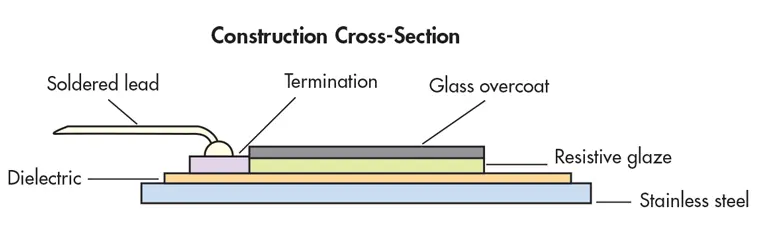
Merging high-temperature, thermal-shock, and vibration ruggedness into a “simple” passive component such as a resistor requires sophisticated design and fabrication, as shown in WDBR series from TT Electronics, which uses a steel substrate.

This impact of thermal shock is greatly aggravated by the on/off cycling of the circuit in which the component is being used, which is typical of automotive applications. The result is thermally induced stress fractures due to repeated expansion/contraction of materials, especially when they have different coefficients of expansion. That’s why the development of a hermetic glass-ceramic seal, which would not be affected by such cycling, was a major material advance in the early 1900s.

Unlike simulations of the effect of higher temperature alone on active- or passive-component performance, modeling the consequences of thermal shock is very difficult. That’s because it often requires determining properties of both the materials and combinations under a variety of test scenarios. In addition, cycling can cause permanent shifts in key parameters of materials.

Designer’s Options Span Operating Sequence to BOM Selection

What options are available to designers? In some cases, systems are deliberately left powered up, or not turned fully off, to limit thermal shock. (Obviously, this is inefficient and often no longer allowed under strict energy mandates.) For example, high-power vacuum tubes often kept “warm,” and theater spotlights (which are still incandescent in most cases) are cut back to about 10-20% of full power when not in use.

A better alternative is use a smarter power controller that slowly turns power on (and sometimes off). In fact, the automated lighting controls now used in most live theaters are programmed to turn the lamp on slowly prior to when the script calls for full lights at a cue point.

Another option is to use passives that are specially designed to live with thermal shock and vibration. For example, the WDBR series of resistors from TT Electronics (12 to 150 Ω) targets applications such as current sensing, dynamic braking, and charge/discharge current limiting in hybrid and electric vehicles. These resistors use steel rather than ceramic for their substrate onto which a thick-film conductor and resistor pattern is printed and fired, and the entire resistor is protected with a high-temperature overglaze (see figure).

Still, the fact remains that the effect of thermal shock is a function of many variables. These include the nominal temperature, the high/low temperature excursion, thermal mass, the specific materials and their temperature coefficients, the mating or bonding between the disparate materials, and amount of associated vibration, to cite a few factors.

There’s actually a quaint reminder of how little was known about the interrelated effects of ambient temperature, thermal shock, and vibration until the mid-20th century, when planes flew higher into thinner, colder air. Metal fatigue was the subject of the dramatic 1951 movie “No Highway in the Sky” starring James Stewart and Marlene Dietrich, in which Stewart portrays an aerospace engineer who discovers why those new planes have been crashing. We’ve come a long way since then, both in our requirements and the ways we meet them. Now, there’s AEC-Q200, the standardized “Stress Test Qualification for Passive Components” for automotive applications.


Related

Recent Posts

Power Design Simulation Tools for Faster Inductor Selection and Loss Optimization

29.6.2026
12

Skeleton Supercapacitor Achieves UL‑certified 3,500 A Peak Current for AI Data Centers

26.6.2026
42

Bourns Planar Transformers for SiC and GaN Gate Driver Isolation

26.6.2026
31

100 V Hybrid Polymer Capacitor from VINA Enesol Targets 48–72 V Power Platforms

26.6.2026
90

Panasonic Releases Relays for IEC 62955 Compliant Single‑Phase EV Wallboxes

25.6.2026
23

Coilcraft Releases 0402 Ferrite-Core Wirewound Chip Inductors for RF and EMI Control

25.6.2026
24

Using a Virtual Anode Thermal Model to Evaluate Miniaturization Risk in Tantalum Capacitors

24.6.2026
39

Bourns Introduced High-Current Coupled Inductor for 48 V Hybrid and IBC Converters

24.6.2026
35

Würth Elektronik Expands Nanocrystalline Cable Cores for Broadband EMI Suppression

23.6.2026
27

Upcoming Events

Jun 30
17:00 - 18:00 CEST

PSMA Capacitor Committee Webinar: High Voltage Pulse Capacitors

Jul 2
17:30 - 18:30 CEST

Can Claude design a production-ready Custom Magnetic Component?

Jul 14
16:00 - 17:00 CEST

EMC Design Essentials: Mastering Varistors and Common Mode Chokes

View Calendar

Popular Posts

  • Boost Converter Design and Calculation

    0 shares
    Share 0 Tweet 0
  • Buck Converter Design and Calculation

    0 shares
    Share 0 Tweet 0
  • LLC Resonant Converter Design and Calculation

    0 shares
    Share 0 Tweet 0
  • Flyback Converter Design and Calculation

    0 shares
    Share 0 Tweet 0
  • MLCC and Ceramic Capacitors

    0 shares
    Share 0 Tweet 0
  • Nvidia Vera Rubin: Why One AI Rack Needs So Many More MLCC Capacitors

    0 shares
    Share 0 Tweet 0
  • Earthing Systems and IEC Classification Explained

    0 shares
    Share 0 Tweet 0
  • Dual Active Bridge (DAB) Topology

    0 shares
    Share 0 Tweet 0
  • SEPIC Converter Design and Calculation

    0 shares
    Share 0 Tweet 0
  • MLCC Case Sizes Standards Explained

    0 shares
    Share 0 Tweet 0

Newsletter Subscription


Passive Components Blog

© EPCI - Leading Passive Components Educational and Information Site

  • Home
  • Privacy Policy
  • EPCI Membership & Advertisement
  • About

No Result
View All Result
  • Home
  • Knowledge Blog
  • Dossiers
  • PCNS

© EPCI - Leading Passive Components Educational and Information Site

This website uses cookies. By continuing to use this website you are giving consent to cookies being used. Visit our Privacy and Cookie Policy.
Go to mobile version