Passive Components Blog
No Result
View All Result
  • Home
  • NewsFilter
    • All
    • Aerospace & Defence
    • Antenna
    • Applications
    • Automotive
    • Capacitors
    • Circuit Protection Devices
    • electro-mechanical news
    • Filters
    • Fuses
    • Inductors
    • Industrial
    • Integrated Passives
    • inter-connect news
    • Market & Supply Chain
    • Market Insights
    • Medical
    • Modelling and Simulation
    • New Materials & Supply
    • New Technologies
    • Non-linear Passives
    • Oscillators
    • Passive Sensors News
    • Resistors
    • RF & Microwave
    • Telecommunication
    • Weekly Digest

    Murata Unveils Lead Disc Ceramic Capacitors for Automotive Safety and EMI Suppression

    SCHURTER Releases Intelligent Three‑Terminal Fuses for Safer Li‑ion Battery Systems

    Can Copper Conductive Inks Displace Silver in Hybrid Electronics?

    Square-Wave Harmonics and RMS Currents in Power Converters

    LeanBOM: Practical Cross‑Technology Capacitor Search by Real Working Conditions

    In the Age of AI, Every Watt Counts: Implications for Components

    Stackpole Extends Resistance Range of 2512 High‑Power Current Sense Resistors

    Wk 27 Electronics Supply Chain Digest

    Littelfuse Announced TVS Diodes for 48 V Automotive Systems

    Trending Tags

    • Ripple Current
    • RF
    • Leakage Current
    • Tantalum vs Ceramic
    • Snubber
    • Low ESR
    • Feedthrough
    • Derating
    • Dielectric Constant
    • New Products
    • Market Reports
  • VideoFilter
    • All
    • Antenna videos
    • Capacitor videos
    • Circuit Protection Video
    • Filter videos
    • Fuse videos
    • Inductor videos
    • Inter-Connect Video
    • Non-linear passives videos
    • Oscillator videos
    • Passive sensors videos
    • Resistor videos

    Ferrite versus Nanocrystalline Power Inductor Cores: Turns, Gap and Size

    KYOCERA AVX Presents Antenna Integrator Studio Tutorial for Antenna Placement and RF Design

    Power Design Simulation Tools for Faster Inductor Selection and Loss Optimization

    EMC‑Compliant PCB and Connector Design Guidelines

    Why Isolated DC/DC Power Supplies Fail Late, Würth Elektronik Podcast

    Designing 800 V DC EMC Filters: Calculation, Simulation and Measurement

    Current Sense Transformer Datasheet and Design‑in Guide

    Designing a USB Type‑C Flyback Planar Transformer with Frenetic’s Planar Tool

    Magnetics Design in High‑Frequency GaN Converters

    Trending Tags

    • Capacitors explained
    • Inductors explained
    • Resistors explained
    • Filters explained
    • Application Video Guidelines
    • EMC
    • New Products
    • Ripple Current
    • Simulation
    • Tantalum vs Ceramic
  • Knowledge Blog
  • Dossiers
    • AI Hardware Dossier
    • Power Converter Dossier
    • Automotive Dossier
    • Capacitor Dossier
    • Resistor Dossier
    • Inductor Dossier
    • Circuit Protection Dossier
  • Suppliers
    • Who is Who
  • PCNS
    • PCNS 2025
    • PCNS 2023
    • PCNS 2021
    • PCNS 2019
    • PCNS 2017
  • Events
  • Home
  • NewsFilter
    • All
    • Aerospace & Defence
    • Antenna
    • Applications
    • Automotive
    • Capacitors
    • Circuit Protection Devices
    • electro-mechanical news
    • Filters
    • Fuses
    • Inductors
    • Industrial
    • Integrated Passives
    • inter-connect news
    • Market & Supply Chain
    • Market Insights
    • Medical
    • Modelling and Simulation
    • New Materials & Supply
    • New Technologies
    • Non-linear Passives
    • Oscillators
    • Passive Sensors News
    • Resistors
    • RF & Microwave
    • Telecommunication
    • Weekly Digest

    Murata Unveils Lead Disc Ceramic Capacitors for Automotive Safety and EMI Suppression

    SCHURTER Releases Intelligent Three‑Terminal Fuses for Safer Li‑ion Battery Systems

    Can Copper Conductive Inks Displace Silver in Hybrid Electronics?

    Square-Wave Harmonics and RMS Currents in Power Converters

    LeanBOM: Practical Cross‑Technology Capacitor Search by Real Working Conditions

    In the Age of AI, Every Watt Counts: Implications for Components

    Stackpole Extends Resistance Range of 2512 High‑Power Current Sense Resistors

    Wk 27 Electronics Supply Chain Digest

    Littelfuse Announced TVS Diodes for 48 V Automotive Systems

    Trending Tags

    • Ripple Current
    • RF
    • Leakage Current
    • Tantalum vs Ceramic
    • Snubber
    • Low ESR
    • Feedthrough
    • Derating
    • Dielectric Constant
    • New Products
    • Market Reports
  • VideoFilter
    • All
    • Antenna videos
    • Capacitor videos
    • Circuit Protection Video
    • Filter videos
    • Fuse videos
    • Inductor videos
    • Inter-Connect Video
    • Non-linear passives videos
    • Oscillator videos
    • Passive sensors videos
    • Resistor videos

    Ferrite versus Nanocrystalline Power Inductor Cores: Turns, Gap and Size

    KYOCERA AVX Presents Antenna Integrator Studio Tutorial for Antenna Placement and RF Design

    Power Design Simulation Tools for Faster Inductor Selection and Loss Optimization

    EMC‑Compliant PCB and Connector Design Guidelines

    Why Isolated DC/DC Power Supplies Fail Late, Würth Elektronik Podcast

    Designing 800 V DC EMC Filters: Calculation, Simulation and Measurement

    Current Sense Transformer Datasheet and Design‑in Guide

    Designing a USB Type‑C Flyback Planar Transformer with Frenetic’s Planar Tool

    Magnetics Design in High‑Frequency GaN Converters

    Trending Tags

    • Capacitors explained
    • Inductors explained
    • Resistors explained
    • Filters explained
    • Application Video Guidelines
    • EMC
    • New Products
    • Ripple Current
    • Simulation
    • Tantalum vs Ceramic
  • Knowledge Blog
  • Dossiers
    • AI Hardware Dossier
    • Power Converter Dossier
    • Automotive Dossier
    • Capacitor Dossier
    • Resistor Dossier
    • Inductor Dossier
    • Circuit Protection Dossier
  • Suppliers
    • Who is Who
  • PCNS
    • PCNS 2025
    • PCNS 2023
    • PCNS 2021
    • PCNS 2019
    • PCNS 2017
  • Events
No Result
View All Result
Passive Components Blog
No Result
View All Result

Coilcraft Releases 0402 Ferrite-Core Wirewound Chip Inductors for RF and EMI Control

25.6.2026
Reading Time: 7 mins read
A A

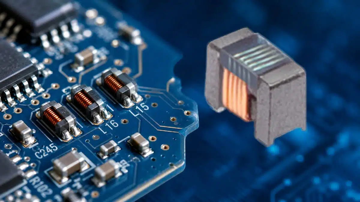
Coilcraft introduces 016008F ferrite-core wirewound chip inductors – ultra‑miniature RF chokes in 0402 (metric 01005) format, designed for high‑frequency circuits where every square millimetre of PCB area counts.

Their combination of very small footprint, high impedance and low DC resistance makes them attractive for designers of compact wireless products who need robust RF isolation and EMI suppression without sacrificing efficiency.

RelatedPosts

Coilcraft Releases High-Current Ferrite Beads for CISPR 25 EMC compliance

Coilcraft Introduces SMT Current Sense Transformers for High‑Performance Power Electronics

Coilcraft Unveils Molded Power Inductors for High‑Current VRMs

Key features and benefits

  • Ultra‑miniature 0402 package – physical dimensions of approximately 0.5 × 0.25 × 0.38 mm, enabling placement in very dense layouts such as smartphones, wearables and IoT RF modules where keep‑out areas are extremely constrained.
  • Ferrite‑core wirewound construction – provides higher inductance and impedance than comparable thin‑film chip inductors in the same footprint, supporting effective RF choke and broadband filtering functions.
  • High impedance for RF isolation – inductance values up to 120 nH in this size allow designers to build efficient high‑frequency isolation networks and EMI suppression paths in cellular and short‑range wireless front‑ends.
  • Exceptionally low DC resistance (DCR) – series DCR specified as low as about 0.18 Ω (typical values according to the manufacturer datasheet), reducing conduction losses and helping preserve signal amplitude and battery life in portable devices.
  • Broad inductance range within one platform – series coverage from roughly 18 nH up to 120 nH, giving RF designers multiple choke options and matching networks without changing footprint or assembly process.
  • Optimized for high‑frequency performance – self‑resonant frequencies specified into the multi‑GHz range (according to manufacturer datasheet), supporting use in contemporary RF bands including sub‑6 GHz wireless systems.
  • Standard reel packaging for volume production – supplied on 7″ tape‑and‑reel with 2000 parts per reel, aligning with automated pick‑and‑place processes in high‑volume consumer and industrial electronics.

In practical terms, this series gives RF and EMC engineers a way to introduce effective inductive elements right at the point of interference generation or signal routing, even in designs where PCB design rules leave almost no room for discrete passives.

Typical applications

The 016008F wirewound chip inductor series targets high‑frequency and space‑constrained designs, with typical use cases including RF isolation, EMI suppression and biasing networks.

  • Cellular RF front‑ends – isolation inductors between PA stages, antenna matching networks, and bias feeds for LNAs and transceiver ICs in smartphones and small modem modules.
  • Short‑range wireless modules – RF chokes and filters in Bluetooth, Wi‑Fi, Thread and proprietary ISM‑band transceiver modules where module outline and component height are tightly specified.
  • IoT and wearable devices – supply decoupling and RF isolation around SoCs, sensors and radios in wearables, asset trackers and health monitoring devices, which often require compact yet robust EMI control.
  • EMI suppression in dense digital boards – insertion in supply or signal lines as part of EMI filter networks to prevent RF energy from propagating between noisy digital domains and sensitive RF sections.
  • Bias tees and DC feed networks – formation of inductive legs in bias‑tee structures used to inject DC bias onto RF lines with minimal impact on RF signal integrity.

Because the inductors are wirewound on a ferrite core, they are especially suited for choke‑type applications where high impedance over a broad frequency range is more important than tight Q control.

Technical highlights

Package, construction and materials

  • Package size: 016008 (metric 0402) chip inductor, with typical dimensions around 0.5 mm × 0.25 mm footprint and 0.38 mm height, according to manufacturer datasheet.
  • Core material: ferrite, selected for high permeability and stable performance at RF frequencies.
  • Construction: wirewound coil on ferrite core in a molded chip body, providing higher inductance density than thin‑film geometries in the same outline.
  • Component mass: roughly 0.10–0.16 mg per inductor, as specified in Coilcraft’s documentation, supporting very light assemblies and minimal impact on mechanical reliability.

Electrical performance (according to manufacturer datasheet)

  • Inductance range: specified inductance values from about 18 nH up to 120 nH at the test frequency, with typical tolerance around ±10% depending on option.
  • DC resistance: extremely low DCR, with series values starting near 0.18 Ω; this is significantly lower than common thin‑film inductors in the same size, which helps minimize insertion loss and heating.
  • Self‑resonant frequency: up to the multi‑GHz range for lower inductance values, enabling use in RF signal paths well into common cellular and WLAN bands (exact values according to manufacturer datasheet).
  • Rated current: current ratings defined per value and limited by temperature rise and core characteristics; designers should refer to the 016008F datasheet curves when dimensioning bias networks and chokes.

Summary table of key parameters

The following table illustrates the type of parameters available for individual part numbers in the 016008F family; exact values should be taken from the Coilcraft datasheet and product pages.

ParameterTypical range / example (per series)
Package size016008 (metric 0402), ~0.5 × 0.25 × 0.38 mm
Inductance values~18 nH to 120 nH according to datasheet
Inductance toleranceAround ±10% (value‑dependent)
DC resistance (DCR)Starting near ~0.18 Ω, value‑dependent
Self‑resonant frequencyUp to multi‑GHz range, value‑dependent
Core materialFerrite
Packaging2000 pcs per 7″ tape‑and‑reel

For design and qualification, engineers should always work with the actual datasheet table that lists electrical characteristics for each ordering code.

Design‑in notes for engineers

When designing with ultra‑small RF inductors such as the 016008F series, layout and value selection are as critical as the component itself.

  • Check operating frequency against self‑resonance – select inductance values whose self‑resonant frequency is well above the operating band to ensure the device behaves as an inductor rather than a resonant element in the application frequency range, using datasheet curves as guidance.
  • Dimension current carefully – consider both DC and AC current components in the choke path and consult Coilcraft’s rated current and temperature‑rise specifications per part number; operating close to current limits can increase losses and shift inductance.
  • Account for parasitics in matching networks – at GHz frequencies, the small package still exhibits parasitic capacitance and lead inductance that affect Q and impedance; designers should include the component’s S‑parameter model when simulating RF matching or bias‑tee circuits.
  • Optimize PCB land pattern and routing – follow the recommended pad geometry from the datasheet to minimize additional series resistance and unwanted capacitive coupling; very short traces and solid ground referencing help preserve intended RF performance.
  • Use value families to standardize layouts – since all inductance options share the same footprint and height, RF teams can design a single pad pattern and swap values during tuning, while purchasing standardizes on one physical family across multiple projects.
  • Consider EMI system‑level behaviour – in EMI suppression use, place inductors as close as possible to noise sources and combine them with complementary capacitors and ground structures to create effective low‑pass or notch filters.[

For qualification, it is good practice to validate a small set of candidate values (for example 18 nH, 39 nH and 75 nH) on the actual PCB using lab measurements of insertion loss, isolation and radiated emissions.

Source

This article is based on Coilcraft’s official information about the 016008F ferrite‑core wirewound chip inductor series and on the related product launch communication provided via RF Design and the manufacturer’s datasheet and product pages.

References

  1. Coilcraft 016008F product page
  2. Coilcraft 016008F series datasheet (PDF)
  3. Coilcraft ferrite core chip inductors family overview

Related

Recent Posts

Square-Wave Harmonics and RMS Currents in Power Converters

14.7.2026
21

In the Age of AI, Every Watt Counts: Implications for Components

13.7.2026
35

RF Filters and Passive Components Enabling the 7 Missile RF Subsystems

9.7.2026
49

Ferrite versus Nanocrystalline Power Inductor Cores: Turns, Gap and Size

9.7.2026
77

YAGEO Presents NANOMET Soft Magnetic Cores for High‑Density Power Conversion

8.7.2026
118

Coilcraft Releases High-Current Ferrite Beads for CISPR 25 EMC compliance

8.7.2026
43

TDK Releases Compact SMD Gate Drive Transformers for xEV

7.7.2026
45

High-Q RF & Microwave MLCCs: A Cross-Vendor Benchmark

2.7.2026
91

YAGEO Presents Single-Phase Common Mode Chokes for Industrial EMI Suppression

1.7.2026
32

Upcoming Events

Jul 21
16:00 - 17:00 CEST

Safety by design: X and Y Interference suppression capacitors for power line filters

Jul 28
8:00 - 11:00 CEST

Post Procurement Testing of EEE Components for LEO Space Applications

Jul 29
17:30 - 18:30 CEST

To Ferrite or to Nanocrystalline in Transformer Design

View Calendar

Popular Posts

  • Boost Converter Design and Calculation

    0 shares
    Share 0 Tweet 0
  • Buck Converter Design and Calculation

    0 shares
    Share 0 Tweet 0
  • Flyback Converter Design and Calculation

    0 shares
    Share 0 Tweet 0
  • LLC Resonant Converter Design and Calculation

    0 shares
    Share 0 Tweet 0
  • YAGEO Announces July 2026 Capacitor Price Increase

    0 shares
    Share 0 Tweet 0
  • MLCC and Ceramic Capacitors

    0 shares
    Share 0 Tweet 0
  • Earthing Systems and IEC Classification Explained

    0 shares
    Share 0 Tweet 0
  • Nvidia Vera Rubin: Why One AI Rack Needs So Many More MLCC Capacitors

    0 shares
    Share 0 Tweet 0
  • MLCCs in the Age of AI: Q2 2026 Market Tightness

    0 shares
    Share 0 Tweet 0
  • Dual Active Bridge (DAB) Topology

    0 shares
    Share 0 Tweet 0

Newsletter Subscription


Passive Components Blog

© EPCI - Leading Passive Components Educational and Information Site

  • Home
  • Privacy Policy
  • EPCI Membership & Advertisement
  • About

No Result
View All Result
  • Home
  • Knowledge Blog
  • Dossiers
  • PCNS

© EPCI - Leading Passive Components Educational and Information Site

This website uses cookies. By continuing to use this website you are giving consent to cookies being used. Visit our Privacy and Cookie Policy.
Go to mobile version