Isolated DC/DC converters seem straightforward on paper, yet many designs only fail when the project is “done” – at EMC, safety review, or after a year of field operation.
This article unpacks why isolated supplies are so prone to late-stage surprises and when it makes sense to switch from discrete designs to integrated isolated power modules based on Würth Elektronik’s MagI³C families and practical project experience.
Key features and benefits of isolated modules
Integrated isolated DC/DC modules combine transformer, switching devices, control loop and usually input/output capacitors in a single package. This means the manufacturer has already co-optimized magnetics, control topology and internal layout for stability and EMC. Isolation requirements such as creepage, clearance, and isolation class are characterized and documented in the module datasheet, and the internal barrier is pre-certified to IEC 62368-1, so you are not starting from scratch with basic safety calculations.
For Würth Elektronik’s MagI³C isolated power modules, three isolated series are available in both through-hole and SMT packages covering input voltages from approximately 2.79 V up to 42 V while meeting IEC 62368 compliance. The EMC behavior is typically better understood than a one-off discrete design, and the internal feedback architecture is implemented to avoid optocoupler current transfer ratio drift completely.
From a project-management perspective, the biggest benefit is not just saved layout effort, but reduced risk of discovering isolation or feedback issues when the layout is frozen and certification slots are booked. For many control or interface boards where power is not the core differentiator, dropping in a pre-certified module lets the design team focus effort on the application circuitry instead of low-level power details.
Why isolation makes everything harder
Non-isolated buck converters operate within a single electrical domain: ground is common, the feedback loop is local, and layout challenges, while real, are confined to one reference system. Once galvanic isolation is introduced, the PCB effectively splits into primary and secondary realms, which cannot share a direct electrical connection. Every assumption about “ground” and signal reference must be revisited, including how the control loop senses and regulates the isolated output.
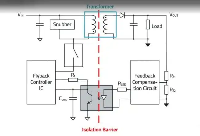
The transformer becomes a central, highly customized element with its own parasitics, core behavior and contribution to EMI, often requiring either a custom-wound part or very careful selection from catalog components. On top of the electrical design, safety standards impose strict creepage and clearance distances along and through the insulation barrier, which depend on working voltage, pollution degree, and chosen isolation class and act as hard pass/fail criteria in safety testing rather than soft recommendations.
IEC 62368-1 is now the dominant standard for industrial and IT equipment, defining isolation types such as functional, basic, reinforced and double insulation. Functional isolation, common in low-voltage industrial bus isolators, prevents ground loops and domain interference but does not protect against electric shock, so any design with a user-accessible interface or hazardous voltages must carefully select the appropriate class and size the spacings accordingly.
Creepage and clearance basics
- Creepage is the distance measured along the surface of the PCB between conductors across the isolation barrier.
- Clearance is the shortest distance through air between those conductors.
- Minimum values depend on working voltage, pollution degree and isolation class defined in the safety standard.
- They must be locked in before layout, because they drive component placement, cut-outs, and keep-outs on the board.
A recurring anti-pattern is discovering a creepage violation only during pre-compliance safety review, when board shape, connector positions and mechanical constraints are already fixed. At that point, “just moving a transformer” can imply a full mechanical and enclosure update, plus another board spin.
The optocoupler problem in discrete isolated designs
In a typical discrete flyback converter with secondary-side regulation, feedback crosses the isolation barrier via an optocoupler. The primary-side controller infers the secondary voltage by monitoring the optocoupler output current and adjusting duty cycle accordingly, a scheme that works well for a new device at room temperature on a quiet bench. The failure mode emerges over time and temperature because optocoupler current transfer ratio is not stable.
CTR degrades with both temperature and operating hours: a device with 100% CTR at 25 °C might drop to around 50% or lower at 85 °C after thousands of hours of elevated-temperature operation. The compensation network is designed around an assumed CTR range, and once the real CTR drifts outside that range, loop stability and regulation margins erode. In practice, this means a supply can pass all initial tests but develop output regulation issues only after long-term deployment in a hot industrial enclosure.
Engineers usually discover this only after field failures, at which point fixing loop stability requires redesigning both the feedback network and sometimes even the transformer or operating point. Because CTR degradation is irreversible, simply swapping in a fresh optocoupler does not represent worst-case conditions, so validating the fix requires explicit margin analysis across the full lifetime range.
Common mitigation strategies
- Design compensation for full CTR range over temperature and lifetime, accepting reduced loop bandwidth and slower transient response to ensure stability at worst case.
- Use primary-side regulation, where the controller infers output voltage from the transformer flyback waveform rather than a secondary measurement, eliminating CTR dependence but also sacrificing tight regulation and load transient performance.
- Replace optocouplers with digital isolators in the feedback path where topology allows, gaining more predictable behavior and aging characteristics but at the cost of additional design complexity and different failure modes.
None of these options are “free”: they trade dynamic performance, accuracy, design time or BOM cost against long-term reliability, and they still leave the team managing multiple failure surfaces, including transformer behavior and layout-induced noise pickup.
Where discrete designers spend their budget
A robust discrete isolated supply consumes engineering time in several tightly coupled areas:
- Transformer design or selection: Choosing turns ratio, leakage inductance and interwinding capacitance requires iteration, and catalog transformers often deviate from datasheet values enough to affect snubber design and EMI.
- Snubber network: A clamp on the primary switch is needed to handle leakage inductance spikes, usually tuned by probing the switch node and iterating until ringing is acceptable – unless a prior simulation provides starting values and sensitivity insight.
- Feedback and compensation: Designing for stability over full temperature and lifetime, especially when using optocouplers, demands conservative compensation and careful routing away from noisy switching nodes.
- Layout for isolation and EMI: Creepage and clearance must be satisfied, high dI/dt loops tightly contained, and sensitive feedback paths separated from switching and transformer fields.
- Verification: EMC emissions/ESD and isolation testing frequently uncover issues that were not visible at bench-level functional tests.
Experienced teams reduce late surprises by building certain steps into their standard flow rather than as optional “nice to have” tasks:
- Simulate the snubber early to get a baseline and understand how leakage inductance and switching speed drive peak stress.
- Plan a transformer evaluation phase where two or three candidate parts are sampled and characterized before finalizing the schematic, acknowledging that real leakage inductance can vary more than catalog numbers.
- Add a formal creepage and clearance review step before releasing the layout to fabrication to catch spacing violations before copper is committed.
These practices do not remove complexity but shift failure discovery earlier, when the cost of change is lower and schedules can still absorb iteration.
Typical applications of isolated DC/DC supplies and modules
Isolated DC/DC converters appear wherever galvanic isolation is required between functional domains or where common-mode noise and ground loops must be controlled. Examples include field instruments on industrial networks, low-voltage bus isolators in PLC and I/O modules, and isolated supplies for gate drivers in power conversion stages.
Functional isolation is often sufficient for low-voltage industrial communication buses where user-accessible hazardous voltages are not present, while reinforced or double isolation is required in systems that bridge to mains or high-voltage domains with possible user contact. In many of these lower-power segments, isolated modules can drop into the role of “local house-keeping supply” feeding measurement, communication or control circuitry without requiring a custom flyback design.
Non-isolated integrated modules, also available in the MagI³C family, address applications where galvanic isolation is not needed but discrete buck complexity and EMC tuning still consume disproportionate design effort. For those designs, similar integration benefits apply, but the trade-off space between module and discrete solution should be evaluated separately from the isolation-specific issues discussed here.
Example use cases
- Isolated power for field transmitters and sensor interfaces on 4–20 mA or industrial Ethernet links.
- Local isolated bias supplies for IGBT or SiC gate drivers in motor drives or PFC stages, where strict creepage, clearance and EMI control are mandatory.
- Small isolated supplies on mixed-signal boards to separate noisy digital domains from sensitive analog measurement sections without sharing a ground reference.
Technical highlights of MagI³C isolated power modules
Within the isolated MagI³C module family, Würth Elektronik offers three series covering a broad low-to-medium power range with both through-hole and surface-mount footprints. Input voltage capability spans from roughly 2.79 V up to 42 V across the range, offering flexibility to support typical 3.3 V, 5 V, 12 V and 24 V industrial rails, among others, while maintaining IEC 62368 compliance.
Internally, these modules integrate:
- A transformer matched to the converter topology, with controlled leakage inductance and interwinding capacitance for predictable EMI.
- Switching devices and control circuitry tuned for the specific transformer and package parasitics.
- On-module input and output capacitors to minimize loop areas and reduce sensitivity to external layout details.
Feedback architectures avoid optocoupler-based regulation and instead use self-oscillating structures or primary-side regulation schemes that do not rely on aging optically coupled components. This removes CTR drift as a long-term variable, leaving the designer to focus on system-level aspects such as input filtering, thermal path, and module placement relative to other circuitry.
Responsibility split with integrated modules
| Aspect | Handled inside module | Remains system designer’s task |
|---|---|---|
| Transformer design | Core selection, turns ratio, parasitics | Mechanical placement, system creepage around module |
| Switching and control | Topology, gate drive, loop stability within rated range | Matching to actual input rail tolerance and load range |
| Isolation barrier | Internal creepage/clearance, certification, IEC 62368 class | Maintaining clearances to other nets and connectors |
| Feedback path | No optocoupler CTR drift; internal architecture fixed | External sensing (if any), selection of output variant |
| Input/output capacitors | Core decoupling and local loop minimization | Bulk capacitance for load steps and bus stability |
| EMC performance | Characterized reference behavior | Input filter design and PCB-level EMI hygiene |
| Thermal behavior | Internal derating and package characteristics | Heatsinking, copper planes, airflow, ambient limits |
Design-in notes for engineers
Start with isolation and safety requirements
Before drawing the schematic or placing a module footprint, determine:
- Working voltage and overvoltage category of the isolated barrier.
- Pollution degree and intended environment, in line with IEC 62368-1.
- Required isolation type: functional, basic, reinforced or double.
Use the spacing tables in the standard to compute minimum creepage and clearance and lock these into your mechanical and PCB rules early. For modules, check the datasheet’s documented isolation class and internal spacings, then add board-level keep-outs and cut-outs as needed around pins, exposed copper and nearby nets.
Managing EMI and snubber behavior
Even with integrated modules, input filtering is not included and remains critical to system EMC. Treat the module as a switching converter with a known emission profile, then design a suitable input filter network:
- Place the input filter close to the module input pins, minimizing loop areas in the high-frequency path.
- Use layout to separate noisy current loops from sensitive analog or digital sections, maintaining solid return planes where possible.
For discrete designs, consider simulating the snubber circuit before bench tuning to understand how leakage inductance and switching speed influence stress peaks. In both cases, be prepared to iterate the filter if EMC testing reveals unexpected coupling through cables, shielding or chassis connections.
Thermal and derating considerations
Derating curves in module datasheets are not optional illustrations but practical limits that reflect real internal temperatures. To keep junction temperatures in a safe range:
- Provide copper areas or thermal vias under and around the module where recommended.
- Verify that the combination of ambient temperature, load current and airflow stays within documented derating curves, especially at 85 °C ambient and above.
An undersized thermal path may pass initial bench tests at room temperature but fail in a sealed industrial enclosure after extended operation. Design reviews should explicitly check worst-case ambient temperature and load, not just nominal conditions.
Deciding between discrete and module
The choice between discrete isolated converters and integrated modules hinges less on “can we do the design?” and more on where the team wants to spend engineering effort and risk budget.
Modules are often the better choice when:
- Product volumes are moderate, and engineering time is more constrained than BOM cost.
- Isolation requirements are stringent and safety certification lead times are tight.
- The isolated supply is not a core differentiator of the design but an enabling function.
Discrete designs remain attractive when:
- Unit volume is high and BOM cost is under close scrutiny, making a tuned discrete solution cheaper per unit once engineering is amortized.
- Custom output voltages, multiple outputs or very tight regulation requirements exceed what fixed-output modules provide.
- Power levels exceed the range where suitable modules are available, pushing toward custom magnetics and higher-power topologies.
If your organization already has a proven, fully characterized discrete isolated design for a particular power level and application, there is no strong reason to replace it with a module. Instead, reserve integrated modules for new designs where the isolated supply would otherwise be a fresh engineering task with its own learning curve and schedule risks.
Conclusion
Isolated DC/DC converters fail late not because the theory is flawed, but because isolation physics, transformer behavior, feedback aging and safety constraints converge at the point where design changes are most expensive. Understanding how creepage, clearance, optocoupler CTR drift and transformer parasitics interact in a real design helps engineers plan mitigation steps and schedule formal reviews before fabrication.
Integrated isolated modules like Würth Elektronik’s MagI³C families shift much of this complexity into a pre-certified building block, leaving designers responsible mainly for input filtering, thermal management and system-level creepage and clearance. For many control and interface applications, this trade-off can convert an unpredictable late-stage risk into a manageable, early design decision, freeing engineering resources to focus on signal integrity, functional safety or application-level innovation.
Source
This article is based on technical information and design recommendations presented by Würth Elektronik in their “Why Isolated Power Designs Fail Late” episode of the Würth Elektronik “What’s Up” podcast and related module documentation according to the manufacturer.
References
- Why Isolated Power Designs Fail Late – Würth Elektronik YouTube episode
- REDEXPERT Power Module Simulator – MagI³C Power Module Designer
- Würth Elektronik MagI³C Power Modules overview
- MagI³C Power Modules reference designs