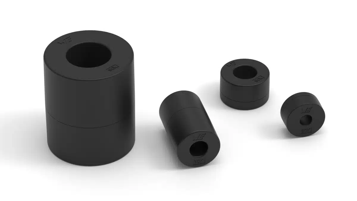
Nanocrystalline cable cores of the WE‑NCC series from Würth Elektronik are designed for broadband suppression of conducted electromagnetic interference on cables and harnesses.
The Würth Elektronik nanocrystalline cable cores complement conventional MnZn and NiZn ferrite cable cores by offering much higher permeability, compact dimensions and stable behavior over a wide temperature range, making them attractive for modern power electronics and industrial applications.
Key features and benefits
- Broadband conducted EMI suppression: WE‑NCC cores provide high impedance from low frequencies upward, making them suitable when both switching‑frequency noise and higher‑frequency interference must be attenuated on the same cable.
- Very high initial permeability: With initial permeability in the range of approximately 30,000 to 90,000 according to the manufacturer, the cores achieve high inductance and impedance even with relatively small core sizes.
- Compact, space‑saving design: The high permeability of the nanocrystalline material allows smaller core dimensions for a given insertion loss compared to many MnZn solutions, which helps when space in cable ducts, control cabinets or inverter housings is tight.
- High magnetic flux density capability: A maximum flux density up to about 1.2 T according to the manufacturer supports effective operation at higher currents before saturation, important in motor drive and inverter cabling.
- High Curie temperature and thermal stability: With Curie temperature specified above 540 °C, the cores exhibit stable magnetic properties over a wide operating temperature range, which improves predictability in harsh industrial environments.
- Weight advantage vs. MnZn: For the same performance, the nanocrystalline material enables lighter cores than typical MnZn ferrites, which is beneficial in mobile equipment or when many cores are used in a harness.
- Wide cable diameter coverage: The series covers cable diameters from around 3.7 mm up to 21.1 mm, allowing the same core family to be used from signal or control wiring up to power cables.
- Part of a broad EMC portfolio: WE‑NCC integrates into Würth Elektronik’s wider EMC ecosystem, including other ferrites for cable assembly, design‑in support, literature and the REDEXPERT online selection tool.
Typical applications
The WE‑NCC nanocrystalline cable cores are aimed at interference suppression on cables in demanding power and industrial environments where conducted EMI needs to be controlled without redesigning the PCB.
Typical use cases include:
- Industrial electronics and automation systems with long cable runs between control cabinets and field devices.
- Inverter technology such as solar inverters, UPS systems or variable‑speed motor drives, where cable‑borne common‑mode noise can cause conducted emissions issues.
- Wind turbine systems with long power and control cables exposed to high dv/dt and noisy switching events.
- Frequency converters and motor drive systems in factory automation, where EMC compliance and motor bearing protection often require additional cable filtering.
- General power electronics and drive systems where retrofitting cores on existing cable harnesses is more practical than modifying the power stage layout.
- Test and troubleshooting setups, where engineers need a quick way to evaluate the impact of additional cable filtering.
In many of these cases, nanocrystalline cores are especially useful when conducted emissions in the lower‑frequency range (close to the switching frequency and its harmonics) are critical, but the solution must still maintain good performance at higher frequencies.
Technical highlights
The most important material and design parameters for WE‑NCC are summarized below. Exact values for individual part numbers should always be taken from the official manufacturer datasheet.
Core and material characteristics
- Nanocrystalline soft‑magnetic material optimized for high permeability and broadband impedance behavior.
- Initial permeability range: approximately 30,000 to 90,000 (typical values according to manufacturer information).
- Maximum magnetic flux density: up to about 1.2 T for efficient operation before saturation in high‑current applications.
- Curie temperature: above 540 °C, which contributes to stable permeability and impedance over a wide operating temperature range and under thermal stress.
In practice, high permeability means that the impedance seen by common‑mode noise currents on the cable builds up quickly even with relatively few turns or with a single pass‑through, which can reduce the number or size of cores needed.
Mechanical and cable‑related parameters
- Cable diameter range: approximately 3.7 mm to 21.1 mm, covering small signal cables, multicore control cables and larger power leads.
- Compact inner and outer geometries that permit installation on existing cable harnesses, typically as snap‑on or clamp‑on style components depending on the specific article.
For EMC design, matching the cable diameter correctly is important: too loose a fit reduces mechanical robustness and may reduce effective coupling; too tight a fit complicates installation and can damage cable insulation.
Broadband impedance behavior
- Compared with conventional MnZn and NiZn ferrite cable cores, the nanocrystalline material exhibits significantly higher impedance at low frequencies, making it effective closer to the switching frequency of modern power converters.
- The impedance profile is broadband, so a single core can help attenuate several frequency ranges, reducing the need for combinations of different ferrite materials.
For design engineers, this broadband behavior can simplify filter schemes: instead of mixing several rings of different materials to cover a wide band, one carefully selected nanocrystalline core may achieve similar or better insertion loss.
Positioning versus MnZn and NiZn ferrites
The table below summarizes the qualitative positioning of nanocrystalline WE‑NCC cable cores compared to typical MnZn and NiZn ferrite cores for cable assembly.
| Property | Nanocrystalline WE‑NCC | Typical MnZn ferrite cores | Typical NiZn ferrite cores |
|---|---|---|---|
| Low‑frequency impedance | Very high | Medium | Low |
| High‑frequency impedance | High (broadband) | Medium | High |
| Core size for given insertion loss | Small | Medium to large | Small to medium |
| Relative weight | Low to medium | High | Low to medium |
| Typical use | Broadband EMI, power cables, industrial drives | Low‑ to mid‑frequency EMI, power lines | High‑frequency EMI, data and signal lines |
This positioning helps in early technology selection before looking up exact part numbers and impedance curves in the datasheet or online tools.
Availability and part numbers
Würth Elektronik offers WE‑NCC nanocrystalline cable cores as a standard catalogue series, with:
- Multiple core sizes and geometries to cover cable diameters from approximately 3.7 mm to 21.1 mm.
- Variants optimized for different insertion loss and mechanical constraints, according to the manufacturer’s product overview.
- Availability from stock, with no minimum order quantity stated for the interference suppression portfolio.
- Free samples on request, which can be useful for EMC troubleshooting or comparison against existing MnZn and NiZn cores.
For specific ordering codes, impedance curves and mechanical drawings, designers and purchasing teams should refer to the official WE‑NCC product page and associated datasheets according to the manufacturer.
A practical workflow is to start from the cable outer diameter and target frequency range, then use Würth Elektronik’s REDEXPERT tool to shortlist suitable WE‑NCC part numbers based on required impedance and insertion loss.
Design‑in notes for engineers
When integrating WE‑NCC nanocrystalline cable cores into a design or retrofit, a few practical guidelines can help maximize EMC performance and avoid surprises during compliance testing.
- Define the EMI problem first
- Clarify whether the issue is common‑mode or differential‑mode noise on the cable.
- Nanocrystalline cable cores are typically most effective for common‑mode noise; for strong differential‑mode issues additional line filters may still be required.
- Select the right core size
- Start from the cable’s outer diameter including insulation and any jacket or shielding.
- Choose a WE‑NCC variant with an inner diameter that gives a snug but not forceful fit; too much mechanical stress can damage cable insulation.
- Consider number of turns and installation method
- A single pass (one turn) is often used on power cables to avoid excessive leakage inductance, but multiple turns through the core can significantly increase low‑frequency impedance on smaller signal cables.
- If multiple turns are used, ensure minimum bending radius of the cable is respected.
- Placement along the cable
- For emission control, cores are often placed close to the noise source, for example at the inverter or drive output, or at the device entrance to reduce noise returning to the mains.
- In some systems, adding cores at both ends of long cables can further improve performance and reduce susceptibility.
- Temperature and saturation considerations
- While nanocrystalline WE‑NCC cores have high Curie temperature and good thermal stability, they can still saturate at high current and low frequency.
- When used with high‑current power cables, check current and frequency against the manufacturer’s curves and consider derating to ensure sufficient margin.
- Integrate into EMC validation workflow
- Use REDEXPERT or manufacturer impedance plots to estimate the impact on conducted emissions before lab testing.
- During pre‑compliance, experiment with different core sizes and positions; the availability of free samples helps optimize the solution without committing to large quantities.
- Think in system terms
- Treat WE‑NCC as part of a broader EMC concept that may include line filters, shield terminations, PCB layout measures and proper grounding.
- Cable cores are often an effective final tuning element but should not replace good layout and grounding practice.
Source
This article is based on information provided by Würth Elektronik in their official press release and related WE‑NCC product documentation, complemented with general engineering context for EMI suppression and cable ferrite selection.