











Passive Components Blog
No Result
View All Result
  • Home
  • NewsFilter
    • All
    • Aerospace & Defence
    • Antenna
    • Applications
    • Automotive
    • Capacitors
    • Circuit Protection Devices
    • electro-mechanical news
    • Filters
    • Fuses
    • Inductors
    • Industrial
    • Integrated Passives
    • inter-connect news
    • Market & Supply Chain
    • Market Insights
    • Medical
    • Modelling and Simulation
    • New Materials & Supply
    • New Technologies
    • Non-linear Passives
    • Oscillators
    • Passive Sensors News
    • Resistors
    • RF & Microwave
    • Telecommunication
    • Weekly Digest

    LeanBOM: Practical Cross‑Technology Capacitor Search by Real Working Conditions

    In the Age of AI, Every Watt Counts: Implications for Components

    Stackpole Extends Resistance Range of 2512 High‑Power Current Sense Resistors

    Wk 27 Electronics Supply Chain Digest

    Littelfuse Announced TVS Diodes for 48 V Automotive Systems

    Spectrum Controls Joins Modelithics Program to Offer High‑Fidelity RF Models for Resistors, Attenuators and Terminations

    RF Filters and Passive Components Enabling the 7 Missile RF Subsystems

    Ferrite versus Nanocrystalline Power Inductor Cores: Turns, Gap and Size

    YAGEO Presents NANOMET Soft Magnetic Cores for High‑Density Power Conversion

    Trending Tags

    • Ripple Current
    • RF
    • Leakage Current
    • Tantalum vs Ceramic
    • Snubber
    • Low ESR
    • Feedthrough
    • Derating
    • Dielectric Constant
    • New Products
    • Market Reports
  • VideoFilter
    • All
    • Antenna videos
    • Capacitor videos
    • Circuit Protection Video
    • Filter videos
    • Fuse videos
    • Inductor videos
    • Inter-Connect Video
    • Non-linear passives videos
    • Oscillator videos
    • Passive sensors videos
    • Resistor videos

    Ferrite versus Nanocrystalline Power Inductor Cores: Turns, Gap and Size

    KYOCERA AVX Presents Antenna Integrator Studio Tutorial for Antenna Placement and RF Design

    Power Design Simulation Tools for Faster Inductor Selection and Loss Optimization

    EMC‑Compliant PCB and Connector Design Guidelines

    Why Isolated DC/DC Power Supplies Fail Late, Würth Elektronik Podcast

    Designing 800 V DC EMC Filters: Calculation, Simulation and Measurement

    Current Sense Transformer Datasheet and Design‑in Guide

    Designing a USB Type‑C Flyback Planar Transformer with Frenetic’s Planar Tool

    Magnetics Design in High‑Frequency GaN Converters

    Trending Tags

    • Capacitors explained
    • Inductors explained
    • Resistors explained
    • Filters explained
    • Application Video Guidelines
    • EMC
    • New Products
    • Ripple Current
    • Simulation
    • Tantalum vs Ceramic
  • Knowledge Blog
  • Dossiers
    • AI Hardware Dossier
    • Power Converter Dossier
    • Automotive Dossier
    • Capacitor Dossier
    • Resistor Dossier
    • Inductor Dossier
    • Circuit Protection Dossier
  • Suppliers
    • Who is Who
  • PCNS
    • PCNS 2025
    • PCNS 2023
    • PCNS 2021
    • PCNS 2019
    • PCNS 2017
  • Events
  • Home
  • NewsFilter
    • All
    • Aerospace & Defence
    • Antenna
    • Applications
    • Automotive
    • Capacitors
    • Circuit Protection Devices
    • electro-mechanical news
    • Filters
    • Fuses
    • Inductors
    • Industrial
    • Integrated Passives
    • inter-connect news
    • Market & Supply Chain
    • Market Insights
    • Medical
    • Modelling and Simulation
    • New Materials & Supply
    • New Technologies
    • Non-linear Passives
    • Oscillators
    • Passive Sensors News
    • Resistors
    • RF & Microwave
    • Telecommunication
    • Weekly Digest

    LeanBOM: Practical Cross‑Technology Capacitor Search by Real Working Conditions

    In the Age of AI, Every Watt Counts: Implications for Components

    Stackpole Extends Resistance Range of 2512 High‑Power Current Sense Resistors

    Wk 27 Electronics Supply Chain Digest

    Littelfuse Announced TVS Diodes for 48 V Automotive Systems

    Spectrum Controls Joins Modelithics Program to Offer High‑Fidelity RF Models for Resistors, Attenuators and Terminations

    RF Filters and Passive Components Enabling the 7 Missile RF Subsystems

    Ferrite versus Nanocrystalline Power Inductor Cores: Turns, Gap and Size

    YAGEO Presents NANOMET Soft Magnetic Cores for High‑Density Power Conversion

    Trending Tags

    • Ripple Current
    • RF
    • Leakage Current
    • Tantalum vs Ceramic
    • Snubber
    • Low ESR
    • Feedthrough
    • Derating
    • Dielectric Constant
    • New Products
    • Market Reports
  • VideoFilter
    • All
    • Antenna videos
    • Capacitor videos
    • Circuit Protection Video
    • Filter videos
    • Fuse videos
    • Inductor videos
    • Inter-Connect Video
    • Non-linear passives videos
    • Oscillator videos
    • Passive sensors videos
    • Resistor videos

    Ferrite versus Nanocrystalline Power Inductor Cores: Turns, Gap and Size

    KYOCERA AVX Presents Antenna Integrator Studio Tutorial for Antenna Placement and RF Design

    Power Design Simulation Tools for Faster Inductor Selection and Loss Optimization

    EMC‑Compliant PCB and Connector Design Guidelines

    Why Isolated DC/DC Power Supplies Fail Late, Würth Elektronik Podcast

    Designing 800 V DC EMC Filters: Calculation, Simulation and Measurement

    Current Sense Transformer Datasheet and Design‑in Guide

    Designing a USB Type‑C Flyback Planar Transformer with Frenetic’s Planar Tool

    Magnetics Design in High‑Frequency GaN Converters

    Trending Tags

    • Capacitors explained
    • Inductors explained
    • Resistors explained
    • Filters explained
    • Application Video Guidelines
    • EMC
    • New Products
    • Ripple Current
    • Simulation
    • Tantalum vs Ceramic
  • Knowledge Blog
  • Dossiers
    • AI Hardware Dossier
    • Power Converter Dossier
    • Automotive Dossier
    • Capacitor Dossier
    • Resistor Dossier
    • Inductor Dossier
    • Circuit Protection Dossier
  • Suppliers
    • Who is Who
  • PCNS
    • PCNS 2025
    • PCNS 2023
    • PCNS 2021
    • PCNS 2019
    • PCNS 2017
  • Events
No Result
View All Result
Passive Components Blog
No Result
View All Result

Using a Virtual Anode Thermal Model to Evaluate Miniaturization Risk in Tantalum Capacitors

24.6.2026
Reading Time: 6 mins read
A A

In this article, Dr. Vladimir Azbel presents a virtual anode thermal model that allows engineers to evaluate how far a tantalum anode design can be minimized while preserving safe forming conditions and reducing the risk of local overheating, stress accumulation, and subsequent DCL instability.

Modern tantalum capacitors are under constant pressure to shrink in size while maintaining or even increasing capacitance and operating voltage. Design miniaturization, however, is not just a question of reducing anode size or pellet mass. It directly affects the local structure of the porous anode, especially the geometry of interparticle necks, and with that the structural and thermal safety margin of the component.

RelatedPosts

From DCL to SSC: Bridging Electrical Symptoms and Structural Indicators in Tantalum Capacitors

Practical Value of Structural Diagnostics for Tantalum Capacitor Anodes

Mechanical SSC Testing as a Structural Diagnostic Tool for Tantalum Capacitor Anodes

Why miniaturization is not just about size

Miniaturization typically involves using higher-CVg powders and adjusting pressing density, anode mass, sintering regime, and forming voltage. At the same time, it unavoidably modifies:

  • The geometry of interparticle necks
  • The local heat flow paths
  • The mechanical connection between tantalum particles

Interparticle necks are critical zones where current flow, heat flow, and mechanical connection all intersect. As the geometrical reserve of these necks decreases, there is increasing risk of:

  • Local overheating
  • Increased mechanical stresses
  • Higher defectivity of the oxide film and interface zone

Interparticle necks are one of the most critical zones of the anode. Current flow, heat flow, and the mechanical connection between tantalum particles all pass through them. During formation, an anodic Ta₂O₅ oxide film grows on the tantalum surface, and this growth does not occur in free volume, but inside a real porous structure constrained by the sizes of the necks, pores, and contact zones.

Therefore, during design miniaturization, it is important to evaluate not only whether the required capacitance is achieved, but also how closely the growing oxide film approaches the geometrical limitations of the interparticle neck. The smaller the geometrical reserve, the higher the sensitivity of the anode to forming conditions, electrolyte conductivity, forming current, and local overheating.

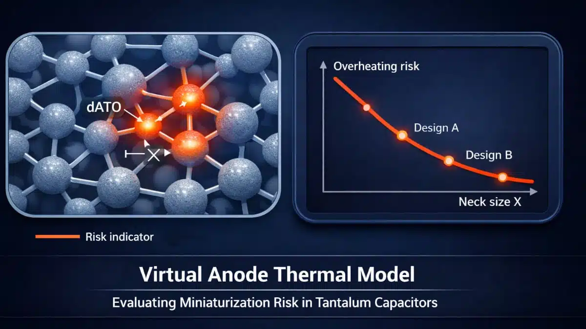
For a visual analysis of this effect, a dimensionless parameter was added to the virtual anode thermal model:

ψ = dATO / X

where dATO is the thickness of the amorphous Ta₂O₅ film, and X is the characteristic size of the metallic neck.

The quantities dATO and X are included in the model parameter Δ, which is used as an indicator of local overheating risk. At the same time, ψ = dATO / X is used as a visual geometrical indicator of their ratio. It shows how closely the thickness of the growing anodic oxide film approaches the characteristic size of the interparticle neck and allows a visual assessment of how changes in neck geometry, under the same forming conditions, affect the value of Δ.

In this sense, the parameter ψ can be considered an indirect indicator of the increasing risk of stress accumulation and possible stress relaxation as forming voltage increases. The more strongly the oxide film occupies the available geometrical scale of the neck, the higher the probability of local growth of mechanical stresses in the Ta / Ta₂O₅ / interface-zone system.

This is especially important for minimized designs. Such a design may maintain the required capacitance and formally meet the electrical requirements, while still having a smaller structural and thermal reserve in the interparticle neck region. In this case, even a small change in electrolyte conductivity or forming current can significantly affect the local thermal balance and the stability of the oxide film.

The virtual model makes it possible to analyze these factors together.

Key idea of the virtual anode thermal model

The virtual model links together:

  • Geometry of the porous structure
  • Interparticle neck size
  • Anodic TaO oxide-film thickness
  • Electrolyte conductivity
  • Forming current and forming voltage

The model introduces a dimensionless parameter that combines oxide-film thickness and neck size as an indicator of local overheating risk. In parallel, a geometrical indicator based on the ratio of oxide-film thickness to neck size provides a clear visual sense of how closely the growing oxide approaches the geometric limits of the neck.

This makes it possible to see not only whether the required capacitance is achieved, but also how much structural and thermal reserve remains in the interparticle-neck region under given forming conditions.

An engineering decision-support tool, not a predictor

A central point of the article is that the model is not intended to give absolute numerical predictions of overheating or DCL degradation. Instead, its purpose is comparative engineering analysis:

  • To evaluate how structural and thermal safety margin changes when geometry or process parameters are varied
  • To compare alternative miniaturization and forming recipes
  • To identify when the design is approaching a critical reduction in structural/thermal reserve

In other words, the model is a decision-support indicator that helps engineers choose more robust technological paths rather than search for a single “correct” number.

Practical questions the model can answer

By combining structural, thermal, and process parameters in one framework, the virtual anode thermal model helps address practical questions such as:

  • How far can we minimize anode geometry without crossing a dangerous threshold for local overheating?
  • Is it more effective to reduce risk by lowering forming current, changing electrolyte conductivity, adjusting forming-voltage steps, or preserving larger neck geometry?
  • How do changes in powder characteristics, sintering, or pressing translate into structural and thermal reserve at the neck level?

A minimized design may formally satisfy electrical requirements (capacitance, DCL, etc.) while having a significantly smaller structural and thermal reserve. The model helps identify such borderline designs early in development.

Model availability

The Excel-based Virtual Anode Thermal Model used in this work is available as an engineering tool for comparative and visual analysis. It allows users to:

  • Visualize how changes in anode geometry and forming conditions affect local overheating risk
  • Combine structural and process parameters in a single analysis framework
  • Support design and process decisions for safer miniaturization

Virtual Anode Thermal Model

https://doi.org/10.5281/zenodo.19482660

Related

Recent Posts

LeanBOM: Practical Cross‑Technology Capacitor Search by Real Working Conditions

13.7.2026
17

In the Age of AI, Every Watt Counts: Implications for Components

13.7.2026
16

RF Filters and Passive Components Enabling the 7 Missile RF Subsystems

9.7.2026
44

From DCL to SSC: Bridging Electrical Symptoms and Structural Indicators in Tantalum Capacitors

7.7.2026
56

High-Q RF & Microwave MLCCs: A Cross-Vendor Benchmark

2.7.2026
81

TAIYO YUDEN Introduced Hybrid Aluminum Capacitors for 48V Automotive Power Supplies

2.7.2026
73

YAGEO Announces July 2026 Capacitor Price Increase

1.7.2026
729

Enabling the 800 V AI Server Era: How C0G High-Voltage MLCC Supports Next-Generation Power Architectures

1.7.2026
161

MLCCs in the Age of AI: Q2 2026 Market Tightness

30.6.2026
456

Upcoming Events

Jul 14
16:00 - 17:00 CEST

EMC Design Essentials: Mastering Varistors and Common Mode Chokes

Jul 21
16:00 - 17:00 CEST

Safety by design: X and Y Interference suppression capacitors for power line filters

Jul 28
8:00 - 11:00 CEST

Post Procurement Testing of EEE Components for LEO Space Applications

View Calendar

Popular Posts

  • Boost Converter Design and Calculation

    0 shares
    Share 0 Tweet 0
  • Buck Converter Design and Calculation

    0 shares
    Share 0 Tweet 0
  • Flyback Converter Design and Calculation

    0 shares
    Share 0 Tweet 0
  • LLC Resonant Converter Design and Calculation

    0 shares
    Share 0 Tweet 0
  • YAGEO Announces July 2026 Capacitor Price Increase

    0 shares
    Share 0 Tweet 0
  • MLCC and Ceramic Capacitors

    0 shares
    Share 0 Tweet 0
  • Earthing Systems and IEC Classification Explained

    0 shares
    Share 0 Tweet 0
  • Nvidia Vera Rubin: Why One AI Rack Needs So Many More MLCC Capacitors

    0 shares
    Share 0 Tweet 0
  • MLCCs in the Age of AI: Q2 2026 Market Tightness

    0 shares
    Share 0 Tweet 0
  • Dual Active Bridge (DAB) Topology

    0 shares
    Share 0 Tweet 0

Newsletter Subscription


Passive Components Blog

© EPCI - Leading Passive Components Educational and Information Site

  • Home
  • Privacy Policy
  • EPCI Membership & Advertisement
  • About

No Result
View All Result
  • Home
  • Knowledge Blog
  • Dossiers
  • PCNS

© EPCI - Leading Passive Components Educational and Information Site

This website uses cookies. By continuing to use this website you are giving consent to cookies being used. Visit our Privacy and Cookie Policy.
Go to mobile version











