Passive Components Blog
No Result
View All Result
  • Home
  • NewsFilter
    • All
    • Aerospace & Defence
    • Antenna
    • Applications
    • Automotive
    • Capacitors
    • Circuit Protection Devices
    • electro-mechanical news
    • Filters
    • Fuses
    • Inductors
    • Industrial
    • Integrated Passives
    • inter-connect news
    • Market & Supply Chain
    • Market Insights
    • Medical
    • Modelling and Simulation
    • New Materials & Supply
    • New Technologies
    • Non-linear Passives
    • Oscillators
    • Passive Sensors News
    • Resistors
    • RF & Microwave
    • Telecommunication
    • Weekly Digest

    TDK Extends SMT Gate Drive Transformers to 1000 V

    Non-Linear MLCC Class II Capacitor Measurements Challenges

    Researchers Demonstrated HfO Anti-Ferroelectric Flexible Capacitors

    Connector Industry Achieves Double-Digit Growth

    Stackpole Unveils Metal Element High Current Chip Jumpers

    Common Mistakes in Flyback Transformer Specs

    Vishay Releases Miniature SMD Trimmers for Harsh Environments

    Würth Elektronik Releases Push-Button and Main Switches

    Littelfuse Unveils High-Precision TMR Angle Magnetic Sensors

    Trending Tags

    • Ripple Current
    • RF
    • Leakage Current
    • Tantalum vs Ceramic
    • Snubber
    • Low ESR
    • Feedthrough
    • Derating
    • Dielectric Constant
    • New Products
    • Market Reports
  • VideoFilter
    • All
    • Antenna videos
    • Capacitor videos
    • Circuit Protection Video
    • Filter videos
    • Fuse videos
    • Inductor videos
    • Inter-Connect Video
    • Non-linear passives videos
    • Oscillator videos
    • Passive sensors videos
    • Resistor videos

    Non-Linear MLCC Class II Capacitor Measurements Challenges

    Percolation Phenomenon and Reliability of Molded Power Inductors in DC/DC converters

    Root Causes and Effects of DC Bias and AC in Ceramic Capacitors

    How to Calculate the Output Capacitor for a Switching Power Supply

    Switched Capacitor Converter Explained

    Understanding Inductor Dot Markings and Their Application in LTspice

    Accelerating Full Bridge LLC Resonant Converter Design with Frenetic AI

    Understanding Switched Capacitor Converters

    Coupled Inductors Circuit Model and Examples of its Applications

    Trending Tags

    • Capacitors explained
    • Inductors explained
    • Resistors explained
    • Filters explained
    • Application Video Guidelines
    • EMC
    • New Products
    • Ripple Current
    • Simulation
    • Tantalum vs Ceramic
  • Knowledge Blog
  • Suppliers
    • Who is Who
  • Events
No Result
View All Result
Passive Components Blog
No Result
View All Result

The Path to Thinner MLCCs and Innovative Capacitor Development

2.4.2025
Reading Time: 4 mins read
A A

This article written by KYOCERA is introducing their material process for thinning the layers of highly reliable MLCC ceramic capacitors and the road to new product development.

As electronic devices become smaller and more sophisticated, multilayer ceramic chip capacitors (MLCCs) are becoming smaller and thinner, and there is a need to develop highly reliable MLCCs that can operate even under harsh conditions.

RelatedPosts

KYOCERA AVX Releases Hermaphroditic WTW and WTB Connectors

Radiation Tolerance of Tantalum and Ceramic Capacitors

KYOCERA AVX Releases 600MHz Band71 Compact SAW Duplexer

However, there are challenges in making the layers thinner, and various technological advances have been required.

Material Process Issues for Thinner Layers

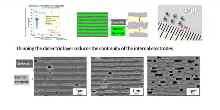
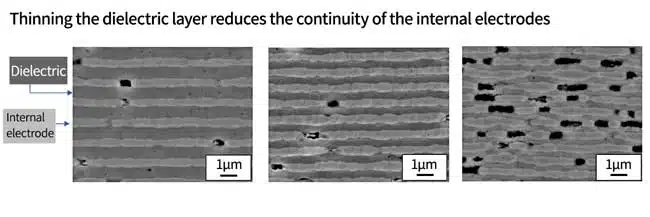
With conventional technology, there was a problem that making the dielectric layer thinner reduced the continuity of the internal electrodes.
As the layers were thinner, unevenness in the internal electrodes, coarse particles in the dielectric layer, impurities, and defects became larger and larger defects, leading to an increase in short circuits, a decrease in voltage resistance, and reduced reliability. It was also assumed that thinning the layers would reduce the number of particles per layer, which would lead to reduced reliability.*1。

 *1: For details on how the number of particles per layer contributes to high reliability, please see Evaluation and Analysis Technology Visualizes Areas of Deterioration

Therefore, it became important to develop new material processes for thinning the layers.

Evolution of Thin Layer Technology

To achieve even thinner layers, it was necessary to evolve each of the elemental technologies for dielectrics, internal electrodes, and firing, as well as to evolve the technology to combine these new elemental technologies.

We will introduce our work on internal electrodes as an example of thin-layer technology.

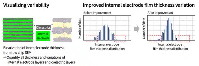
The raw chip SEM was binarized to quantify the thickness and variation of the internal electrode layer and dielectric layer. The variation of the internal electrode film thickness was improved by reducing the diameter of the Ni particles and improving the particle size distribution, co-material size, plate cylinder design, and paste rheology (red frame in the graph).

Thus, designing for variation/local defects is particularly important in thin layer technology.

Continuity results of internal electrodes using thin layer technology

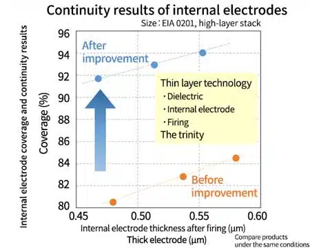
By combining improvements to the internal electrodes with thin-layer technology for dielectrics and firing, we were able to achieve an improvement of approximately 10% and coverage from the 80% range to the 90% range at the same thickness ratio (EIA 0201 size, high-layer stack).

Furthermore, as shown in the left figure, even with an internal electrode thickness of 0.45 μm, good continuity of over 90% coverage was maintained, and we were able to achieve a thin dielectric layer and high coverage and thin internal electrode layer.

However, since the internal electrode is still thicker than the dielectric, it is believed that the internal electrode can be made even thinner. We will continue to work on developing even thinner layer technology.

New Product Development and World-Leading Announcements

The development of the material process, evaluation and analysis technologies led to the release of an EIA 0201 size product with a capacitance value of 10μF, the highest capacitance class in the industry and a world-leading announcement.

Temperature CharacteristicsX5R (EIA)
Operating Temperature Range-55℃ to +85℃
Temperature Coefficient±15%
Capacitance10μF
Capacitance ToleranceK(±10%)、M(±20%)
Dissipation Factor10% MAX.
IR50MΩ・μF MIN.
Rated Voltage4.0Vdc

MLCC size trends

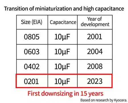
In terms of the development of MLCCs worldwide, EIA 0805 10μF was developed in 2001, EIA 0603 10μF in 2004, and then EIA 0402 10μF in 2008, four years later (according to Kyocera). And the EIA 0201 10μF developed by Kyocera in 2023 was the first downsizing in 15 years.

Kyocera will continue to develop MLCCs in line with market trends toward smaller size and higher capacity.

Related

Source: KYOCERA

Recent Posts

Non-Linear MLCC Class II Capacitor Measurements Challenges

19.8.2025
14

Researchers Demonstrated HfO Anti-Ferroelectric Flexible Capacitors

19.8.2025
7

Common Mistakes in Flyback Transformer Specs

15.8.2025
21

High Voltage MLCCs Meeting the Growing Demand for Efficiency in Power Conversion

12.8.2025
107

KYOCERA AVX Releases Hermaphroditic WTW and WTB Connectors

8.8.2025
13

Radiation Tolerance of Tantalum and Ceramic Capacitors

8.8.2025
70

TDK Releases Compact Polypropylene Film Capacitors for Resonant Topologies

7.8.2025
33

Percolation Phenomenon and Reliability of Molded Power Inductors in DC/DC converters

6.8.2025
41

Root Causes and Effects of DC Bias and AC in Ceramic Capacitors

6.8.2025
56

Knowles Unveils High-Performance Safety-Certified MLCC Capacitors

6.8.2025
43

Upcoming Events

Aug 27
17:00 - 18:00 CEST

Capacitor Assemblies for High-Power Circuit Designs

Sep 3
15:30 - 17:30 CEST

How to Choose Your Magnetic Supplier

Sep 16
17:00 - 18:00 CEST

EMI Shielding Challenges

Sep 22
September 22 @ 13:00 - September 25 @ 15:15 EDT

Pre Cap Visual Inspection per Mil-Std-883 (TM 2017)

Sep 30
September 30 @ 12:00 - October 2 @ 14:00 EDT

MIL-Std-883 TM 2010

View Calendar

Popular Posts

  • Buck Converter Design and Calculation

    0 shares
    Share 0 Tweet 0
  • Boost Converter Design and Calculation

    0 shares
    Share 0 Tweet 0
  • Flyback Converter Design and Calculation

    0 shares
    Share 0 Tweet 0
  • LLC Resonant Converter Design and Calculation

    0 shares
    Share 0 Tweet 0
  • What is a Dielectric Constant and DF of Plastic Materials?

    4 shares
    Share 4 Tweet 0
  • Ripple Current and its Effects on the Performance of Capacitors

    3 shares
    Share 3 Tweet 0
  • Dual Active Bridge (DAB) Topology Explained

    0 shares
    Share 0 Tweet 0
  • How to Design an Inductor

    0 shares
    Share 0 Tweet 0
  • MLCC Case Sizes Standards Explained

    0 shares
    Share 0 Tweet 0
  • MLCC and Ceramic Capacitors

    0 shares
    Share 0 Tweet 0

Newsletter Subscription


Passive Components Blog

© EPCI - Leading Passive Components Educational and Information Site

  • Home
  • Privacy Policy
  • EPCI Membership & Advertisement
  • About

No Result
View All Result
  • Home
  • Knowledge Blog
  • Premium Suppliers

© EPCI - Leading Passive Components Educational and Information Site

This website uses cookies. By continuing to use this website you are giving consent to cookies being used. Visit our Privacy and Cookie Policy.
Go to mobile version