


Vishay’s new CRCW0201-AT e3 series extends the company’s thick film chip resistor portfolio into the ultra-compact 0201 size with full AEC-Q200 qualification.
The series targets space-constrained automotive, industrial, and telecom boards where designers need stable performance, robust environmental behavior, and automotive-grade qualification.
Key features and benefits
The Vishay CRCW0201-AT e3 thick film chip resistor series combines a very small footprint with parameters tailored to high-volume automotive and industrial applications.
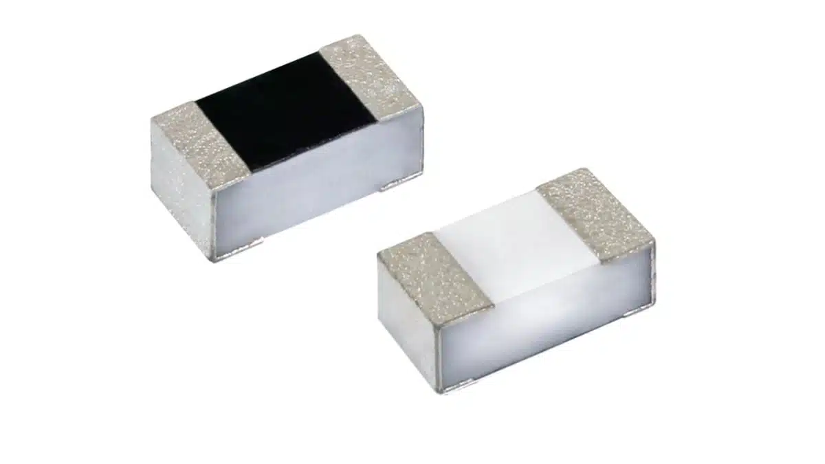
- Ultra-compact 0201 case size (approx. 0.6 mm × 0.3 mm × 0.23 mm), enabling extremely dense layouts and fine-pitch routing in compact ECUs and modules.
- AEC-Q200 qualified thick film technology, suitable for automotive environments and other high-reliability use cases where qualification evidence is required.
- Rated power of 0.05 W at 70 °C, which is typical for 0201 but sufficient for signal-level and many pull-up/pull-down functions in tightly packed circuits.
- Maximum operating voltage of 30 V, covering most low-voltage rails and I/O circuits in automotive and industrial electronics.
- Broad resistance range from 10 Ω to 1 MΩ plus a 0 Ω jumper option, allowing one family to cover a wide variety of biasing, termination, and configuration needs.
- Available tolerances of ±1% and ±5%, so the same platform can serve both cost-sensitive and moderately precision-critical nodes.
- TCR of ±200 ppm/K, adequate for general-purpose signal, bias, and termination resistors where moderate temperature dependence is acceptable.
- Operating temperature range from −55 °C to +155 °C, allowing use close to hot components and inside harsh under‑hood or industrial environments.
- RoHS-compliant and halogen-free construction with pure matte tin terminations, simplifying environmental compliance and solder process compatibility across Pb-free and legacy lines.
- Protective coating designed for electrical, mechanical, and climatic protection, helping maintain resistance stability under humidity, thermal cycling, and mechanical stress.
For purchasing teams, the combination of AEC-Q200 qualification, wide resistance range, and standard 0201 footprint simplifies BOM consolidation and second-sourcing strategies across multiple projects.
Typical applications
Vishay positions the CRCW0201-AT e3 resistors primarily for automotive, industrial, and telecommunications designs, but the feature set makes them useful wherever very small, general-purpose chip resistors are required.
Typical use cases include:
- Automotive electronics
- High-density control units (body electronics, ADAS ECUs, infotainment, gateway modules)
- Sensor interfaces and signal conditioning stages
- Pull-ups, pull-downs, feedback networks, and simple RC filters on space‑limited PCBs
- Industrial systems
- Compact IO modules and PLC cards
- Smart sensors and transmitters with miniaturized PCBs
- Industrial communication interfaces (fieldbus, Ethernet-based industrial networks)
- Telecommunications and networking
- High-density line cards and backplane modules
- Termination networks and biasing in SerDes and transceiver circuits
- RF front-end and low-power baseband circuits where 0201 helps reduce parasitics and routing length
- Consumer and portable electronics
- Wearables, hearables, and ultra-compact consumer devices where board space is at a premium
- Small sensor nodes and IoT modules with aggressive miniaturization targets
In most of these roles, the resistors serve as general-purpose passive components rather than function-defining elements, but the tiny footprint and automotive qualification can be decisive in platform-level design decisions.
Technical highlights
While the family is positioned as a general-purpose thick film resistor, several technical details are important for design-in:
- Case size and footprint
- Case size: 0201 (imperial), metric code RR0603M
- Typical dimensions: ~0.6 mm × 0.3 mm × 0.23 mm according to the manufacturer datasheet
- Electrical parameters (according to manufacturer datasheet and NPI information)
- Resistance range: 10 Ω to 1 MΩ plus 0 Ω jumper
- Tolerances: ±1%, ±5%
- TCR: ±200 ppm/K
- Rated dissipation at 70 °C: 0.05 W
- Maximum operating voltage (AC RMS/DC): 30 V
- Environmental and reliability characteristics
- Operating temperature range: −55 °C to +155 °C
- AEC-Q200 qualified for automotive applications
- Protective coating for electrical, mechanical, and climatic robustness
- Pure matte tin plating over Ni barrier, suitable for reflow or vapor phase assembly in Pb-free and mixed soldering environments
From a practical perspective, ±200 ppm/K TCR means that for a 10 kΩ resistor over a 100 K temperature swing, the resistance change is on the order of a few percent, which is typically acceptable for biasing, pull-ups, and terminations, but not for precision sensing. Designers needing tighter drift or higher stability should consider pairing these 0201 devices with precision references or reserve them for non-critical nodes.
The 0 Ω jumper option simplifies layout variants: it allows using the same footprint for configuration links and simple option selection without needing a separate jumper footprint in a different package size.
Design-in notes for engineers
Moving to 0201 resistors introduces several practical considerations beyond pure electrical parameters. The CRCW0201-AT e3 series is designed to operate reliably when those aspects are handled correctly in layout and manufacturing.
PCB layout and assembly
- Pad design and stencil
- Use the land pattern and solder mask recommendations from the Vishay datasheet to avoid tombstoning and skew during reflow.
- Pay attention to paste volume; for 0201 components, small variations in solder paste deposition can strongly influence wetting forces.
- Placement accuracy
- Ensure pick-and-place machines are capable of handling 0201 packages with appropriate vision and placement tolerances.
- Component libraries in the placement system should reflect the exact body size and pick-up point to reduce misalignment.
- Reflow profile
- Follow Vishay’s guidance for maximum component and solder temperatures, ensuring that the component thermal mass is taken into account.
- Avoid overly aggressive ramp rates that may introduce mechanical stress on the ceramic substrate.
Electrical and thermal considerations
- Power derating
- The 0.05 W rating at 70 °C implies that at higher ambient or local hotspot temperatures, the allowable power dissipation must be reduced according to the datasheet derating curve.
- In practice, keeping continuous power significantly below the maximum helps maintain long-term stability, especially in dense automotive ECUs.
- Voltage and surge behavior
- With a 30 V operating voltage rating, the devices are well suited for low-voltage logic, sensor lines, and general signal paths, but not for high-voltage nodes or surge paths.
- For circuits with ESD or transient exposure, combine these resistors with appropriate TVS diodes or surge elements rather than relying on the resistor itself as a protection device.
- Precision and drift
- The ±1% tolerance is sufficient for many feedback and gain-setting networks in non-critical analog stages, but designs requiring tight absolute accuracy or long-term drift control may need alternative resistor technologies or external calibration.
- When using these resistors in temperature-sensitive circuits, model the ±200 ppm/K TCR and expected ambient range to confirm that error budgets remain acceptable.
Source
This article is based on technical information and specifications provided in the official Vishay Intertechnology press release and associated product documentation for the CRCW0201-AT e3 series. For detailed and up-to-date parameters, designers should always consult the latest manufacturer datasheet.


