


This article explains very basic definition of What is a Capacitor ?, its main application and technologies.
Key Takeaways
- A capacitor is an electrical component that stores energy in an electrostatic field, consisting of two conductive plates separated by a dielectric material.
- Capacitance measures the amount of charge stored relative to the voltage, expressed with the formula C = Q / V.
- Capacitors come in various technologies, including Electrostatic, Electrolytic, and Supercapacitors, each with unique construction and features.
- Capacitors serve multiple applications, such as bypassing, coupling, filtering, and energy storage in circuits.
- Practical capacitor sizes include picofarads, nanofarads, and microfarads, with the farad as the SI unit of capacitance.
Related article: Choosing the Right Capacitor: The Importance of Accurate Measurements
Capacitor Definition
Capacitors are passive electrical components to store electric energy
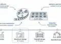
A capacitor is made from electrical conductive electrodes that are separated by an insulator. The insulating layer is called a dielectric. Although all capacitors share the same basic principle components, the material choice, configurations and features can vary widely.
Overview of common capacitors symbols can be find in related article here.
A capacitor is able to store energy in an electrostatic field that is generated by a potential difference across the conducting electrodes. So when an electrode is subject to a voltage, one plate of the capacitor will collect positive charge while the other will be negatively charged. The ratio of this electric charge and the potential difference (voltage) is called the capacitance and it is expressed in farads. The leaking current through the dielectric is called the leakage current.
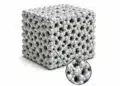
A capacitor is formed by two parallel conductive plates separated by a dielectric material. The dielectric can be air, ceramic, plastic, or other insulating substances. When connected to a voltage source, positive charges accumulate on one plate and negative charges on the other, creating a potential difference and an electric field.
Capacitance Definition and Equations
Capacitance (C) is defined as the ratio of the charge (Q) stored on the plates to the voltage (V) across them:
C = Q / V
Capacitance can also be calculated from physical dimensions:
C = ε S / d
Where:
ε = Permittivity of free space (≈ 8.85 × 10⁻¹² F/m)
S = Area of the plates
d = Distance between the plates
Units and Practical Capacitor Sizes
The SI unit of capacitance is the farad (F). However, most practical capacitors are much smaller:
| Unit | Symbol | Value |
|---|---|---|
| Picofarad | pF | 10−12 F |
| Nanofarad | nF | 10−9 F |
| Microfarad | μF | 10−6 F |
Capacitor Technologies
We can split fixed capacitor technologies further into the three main groups that substantially differ in its construction and features:
- Electrostatic Capacitors
- Electrolytic Capacitors
- Supercapacitors (electrochemical capacitors)
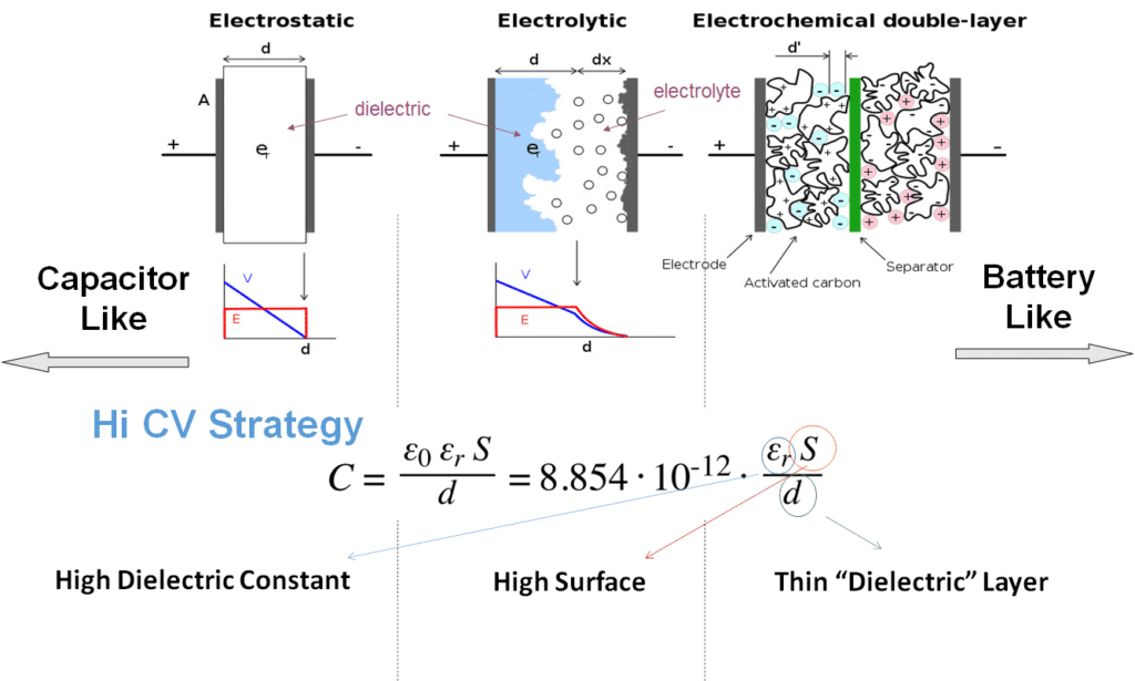
These are the “typical” capacitors as we can imagine on the first moment with a “conventional” construction Metal – Insulator – Metal consisting two electrodes separated by a dielectric material. The capacitor are non-polar so it does not matter how these are connected to the circuit and it can be also used at AC voltage (just note AC and DC voltage range may differ as we discussed in the first part of the course). High capacitance value is achieved by selection of materials with high permittivity (ceramic class II materials). High withstand voltage is achieved by selection of dielectric materials with high dielectric strength (organic film materials) – but of course permittivity and capacitance is lower.
These capacitors are achieving very high capacitance values due to formation of very high surface of electrode. Such very fine, etched/micro porous high surface area is however very difficult to contact from the second side, thus a conductive medium-electrolyte is used to enable electrical contact to such surface. Downsize of this configuration is that it works in one direction – so these are polar DC devices, the internal structure has higher losses that also may impact its frequency and temperature dependency.
Supercapacitors are in fact not “true capacitors” but a structure with features between capacitors and batteries. There is no classical dielectric layer, its capacitance is created by a charge on electrode interface. The charge is accumulated just within few atomic layers and thus the “virtual dielectric” is very thin resulting in huge capacitance value. However – the structure is limited to cell voltage (between 0.8 and 3V typically) and it is only DC with limited AC operation. Thus it is suitable as DC energy storage capacitor but it can not be used like AC filtering capacitor in DC/DC converters.
We can split fixed capacitor technologies further into the three main groups that substantially differ in its construction and features:
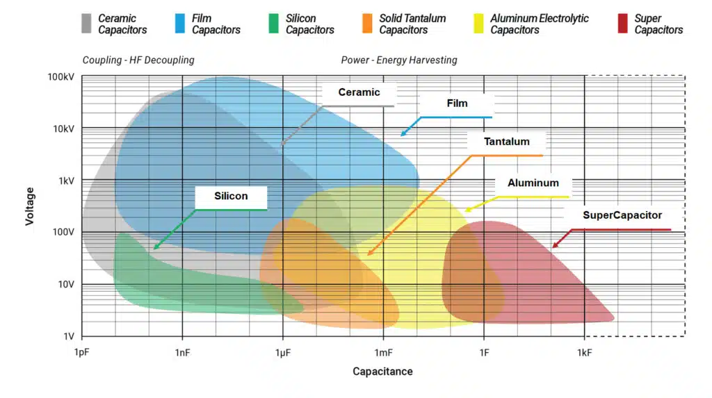
Capacitor Technologies Capacitance versus Voltage Capabilities
Finally for the introduction here is an overview of capacitance versus voltage capability of the main capacitor technologies in mass volume market:
Applications – What is it good for ?
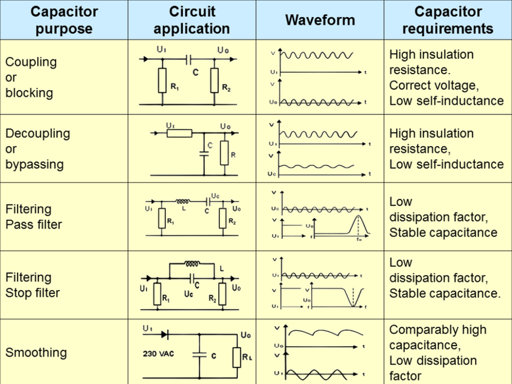
Capacitors are common elements in electrical circuits with number of applications and different requirements such as:
Here are further links with more insights about the capacitor circuit function and its selection guide:
- Bypass Capacitors: Providing clean power to devices by filtering noise and suppressing transients on supply lines.
- Decoupling Capacitors: Isolating sensitive components from noise by storing and releasing energy to maintain steady supply voltage during transients.
- DC-Blocking Capacitors: Preventing unwanted DC offsets from corrupting the AC or RF signals in these systems.
- DC Link Capacitors: acting as buffers that smooth power delivery and minimize ripples.
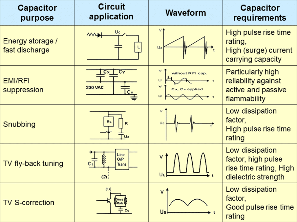
- Safety Capacitors: Protecting circuits and mitigate energy hazards in high-voltage systems.
- EMI Filters: suppressing electromagnetic noise generated by switched-mode power supplies, motor drives, and other electronics.
- Snubber Capacitors: Absorbing voltage spikes, limiting over-voltages.
- Resonant Capacitors: Leveraging this resonance to oscillate at specific frequencies, storing and releasing energy.
- Flying Capacitors: Transferring charges between different voltage potentials in multi-level power inverters.
- Bootstrap Capacitors: Enabling efficient high-side switching in half-bridge and full-bridge power converters.
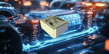
- Power Back-Up and Load Management: Capacitors in battery-powered devices provide backup power in the event of disconnection or supply alternating current (AC) voltage for devices with heavy switching currents.
- PFC Power Factor Correction Capacitors: Power factor correction circuits are used to minimize reactive power and enhance the efficiency with which inductive loads consume AC power.
Basic Charge Storage and Discharge
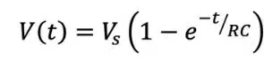
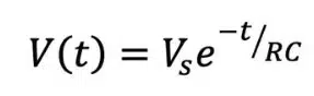
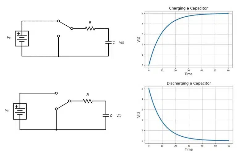
When connected to a direct current (DC) voltage source, capacitors charge almost instantaneously, but they can discharge just as fast if shorted; however, with some resistance in place, the rate of charge and discharge is exponential rather than direct (Figure 4).
The charging formula is expressed as:
The discharging formula is expressed as:
Oscillators, waveform shapers and low-discharge power backup circuits are examples of electronics that leverage controlled charge and discharge rates.
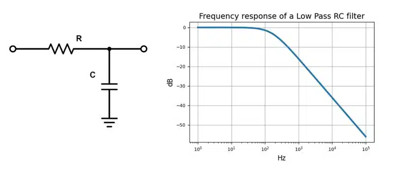
Bypassing and Low-Pass Filtering
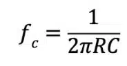
When placed in parallel with a signal path, capacitors take on a bypassing function. They allow DC to continue along the wire, but they divert high-frequency signal components to ground. In other words, capacitors play a role in low-pass filters, offering a low-impedance path for high-frequency signals to ground. In an RC low-pass filter (Figure 4), impedance decreases as frequency increases, so the ratio of VI to VO depends on the value of R, C and the signal frequency. When signals are low frequency and high impedance, energy goes to the output. When signals are high frequency and low impedance, energy is sent to ground.
Frequency cutoff for an RC low-pass filter is expressed as:
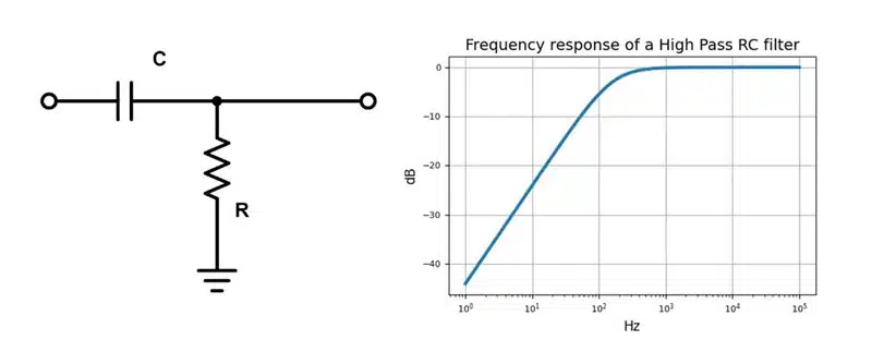
Coupling and High-Pass Filtering
When placed in series with the signal path, rather than in parallel, capacitors take on a different bypassing role. In this arrangement, they block DC while allowing AC signals to pass through the circuit. This function is called DC blocking or AC coupling.
The frequency cutoff for an RC high-pass filter is the same as for a RC low-pass filter:
In Figure 5, low-frequency signals see an impedance that is higher than R, so they go to ground. High-frequency signals see an impedance lower than R, resulting in a high-frequency output.
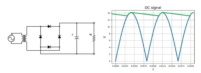
Smoothing Circuit
As mentioned, controlled capacitor charging and discharging serves multiple uses in electronics. For example, a full wave rectifier can use a capacitor to smooth rectified DC pulses and produce a more consistent DC output with less ripple (Figure 6).
The blue DC pulse is the result of a 60Hz AC signal at 10V root-mean-square (rms) passing through a rectifier. The smoothing capacitor charges at the top of each pulse and discharges until the next pulse rises, when it recharges the capacitor. The output across the load is noted in green on the plot.
Timing and Waveform Shaping
A discussion of timing and waveform shaping is best with context. Here, we’ll use an RC relaxation oscillator (Figure 7). In these circuits, the voltage across the capacitor relaxes toward a time-varying target voltage.
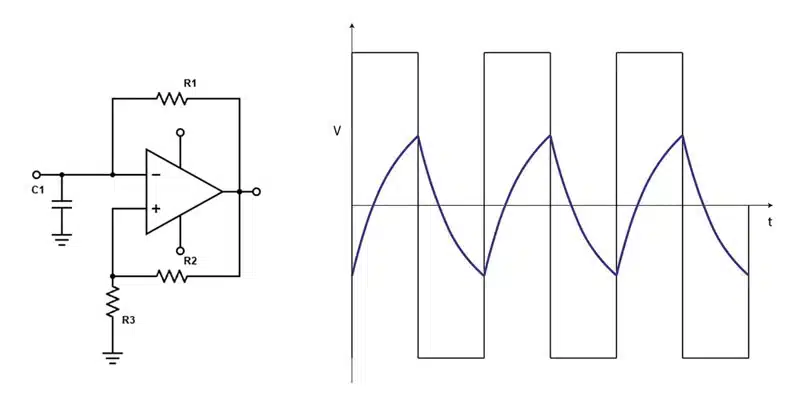
The capacitor is charged through a resistor and discharged when it reaches a certain threshold value, and this cycle repeats continuously. An amplifier, wired with positive feedback, controls the charging and discharging of the capacitor by acting like a switch triggered by the voltage threshold. The amplifier is also responsible for providing gain to the oscillator to maintain the oscillation. Figure 7 shows the switching behavior of the square wave output. Charging and discharging is represented by the blue waveform.
Further read:
- Selection of Capacitors for DC/DC Converters
- Choosing the Right Capacitor: The Importance of Accurate Measurements
Frequently Asked Questions about Capacitors
A capacitor is a passive electronic component that stores electrical energy in an electrostatic field. It consists of two conductive plates separated by a dielectric material such as ceramic, plastic, or air.
When voltage is applied across its plates, one plate accumulates positive charge and the other negative charge. The ratio of stored charge to voltage is called capacitance, measured in farads (F).
The main categories are electrostatic capacitors (ceramic, film), electrolytic capacitors (aluminum, tantalum), and supercapacitors. Each type differs in construction, polarity, capacitance range, and applications.
Capacitors are used for filtering, decoupling, energy storage, power factor correction, EMI suppression, timing circuits, and waveform shaping in both AC and DC systems.
Capacitance is measured in farads (F), but practical capacitors are usually rated in microfarads (µF), nanofarads (nF), or picofarads (pF).
How to Understand and Use Capacitors
- Identify the capacitor type
Check whether it is ceramic, film, electrolytic, or supercapacitor. This determines polarity, voltage rating, and application suitability.
- Read the capacitance value
Capacitance is marked in µF, nF, or pF. Ensure the value matches the circuit requirements for filtering, timing, or energy storage. In many cases capacitors are marked on its body with a code symbol that has to be checked with manufacturer data sheet. Sometimes there is no code at all such in the case of small MLCC ceramic capacitors.
- Check the voltage rating
Always use a capacitor with a voltage rating higher than the maximum circuit voltage to prevent breakdown. Consider voltage derating where appropriate to avoid degradation in life, surge current or harsh environment exposure.
- Place the capacitor correctly
For electrolytic capacitors, observe polarity (positive and negative leads). Non-polar capacitors can be placed in either direction.
- Apply in circuit
Use capacitors for decoupling (stabilizing voltage), filtering (removing noise), coupling (passing AC while blocking DC), or energy storage. Online modeling tools such as PSpice can be of help for the first design ideas. If possible use the concrete capacitor model from the library / capacitor manufacturer library for high fidelity simulation. Use of ideal capacitor in the simulation model may not reflect the real resonance frequency, oscillation or surge current issues.