Passive Components Blog
No Result
View All Result
  • Home
  • NewsFilter
    • All
    • Aerospace & Defence
    • Antenna
    • Applications
    • Automotive
    • Capacitors
    • Circuit Protection Devices
    • electro-mechanical news
    • Filters
    • Fuses
    • Inductors
    • Industrial
    • Integrated Passives
    • inter-connect news
    • Market & Supply Chain
    • Market Insights
    • Medical
    • Modelling and Simulation
    • New Materials & Supply
    • New Technologies
    • Non-linear Passives
    • Oscillators
    • Passive Sensors News
    • Resistors
    • RF & Microwave
    • Telecommunication
    • Weekly Digest

    Percolation Phenomenon: Degradation of Molded Power Inductors in DC/DC Converters

    Molex Acquires Smiths Interconnect

    Murata Integrates Component Models into Cadence EDA Tools

    Wk 42 Electronics Supply Chain Digest

    Stackpole Introduces Automotive Thick Film Wide Termination Chip Resistors

    September 2025 ECIA US Components Sales Sentiment Continues in Optimism

    Bourns Release Automotive 4-Terminal Shunt Resistors

    Bourns Releases High Inductance Common Mode Choke

    Vishay Releases Automotive TO-220 Case 50W Thick Film Power Resistor

    Trending Tags

    • Ripple Current
    • RF
    • Leakage Current
    • Tantalum vs Ceramic
    • Snubber
    • Low ESR
    • Feedthrough
    • Derating
    • Dielectric Constant
    • New Products
    • Market Reports
  • VideoFilter
    • All
    • Antenna videos
    • Capacitor videos
    • Circuit Protection Video
    • Filter videos
    • Fuse videos
    • Inductor videos
    • Inter-Connect Video
    • Non-linear passives videos
    • Oscillator videos
    • Passive sensors videos
    • Resistor videos

    Percolation Phenomenon: Degradation of Molded Power Inductors in DC/DC Converters

    Connector PCB Design Challenges

    Efficient Power Converters: Duty Cycle vs Conduction Losses

    Ripple Steering in Coupled Inductors: SEPIC Case

    SEPIC Converter with Coupled and Uncoupled Inductors

    Coupled Inductors in SEPIC versus Flyback Converters

    Non-Linear MLCC Class II Capacitor Measurements Challenges

    Percolation Phenomenon and Reliability of Molded Power Inductors in DC/DC converters

    Root Causes and Effects of DC Bias and AC in Ceramic Capacitors

    Trending Tags

    • Capacitors explained
    • Inductors explained
    • Resistors explained
    • Filters explained
    • Application Video Guidelines
    • EMC
    • New Products
    • Ripple Current
    • Simulation
    • Tantalum vs Ceramic
  • Knowledge Blog
  • Suppliers
    • Who is Who
  • PCNS
    • PCNS 2025
    • PCNS 2023
    • PCNS 2021
    • PCNS 2019
    • PCNS 2017
  • Events
No Result
View All Result
Passive Components Blog
No Result
View All Result

Introduction to RFID Technology

2.5.2025
Reading Time: 5 mins read
A A

This article based on Murata blog briefly explains What is RFID and how RFID works, and RFID frequency bands.

What is RFID?

RFID (radio frequency identification) is automatic recognition technology that uses wireless communication. Generally, a system or a part that uses an IC tag to identify or control various items via wireless communication is called RFID. Here, a description is given mainly of the features of RFID and the principle of wireless communication in order to provide basic knowledge concerning RFID.

RelatedPosts

Percolation Phenomenon and Reliability of Molded Power Inductors in DC/DC converters

Inductor Resonances and its Impact to EMI

Rogowski Coil Current Sensor Explained

Features

Data can be read at long distance

By using wireless communication, data can be read at distance of several meters. Data can be read from a tag that is in a high, relatively inaccessible place. Inventory count in a large store or a storehouse can be easily done while securing operators safety.

Multiple tags can be read at once

RFID obviates the need to hold each item one by one in order to read the data. It enables the data in all of the tags to be read at once by simply passing the scanner over the tags. This greatly reduces the time required to carry out stocktaking, etc.

Data can also be read from outside the box

Since data is communicated via radio waves, it can be read from outside the packing box without opening the box, even when a tag is attached to the product. Unlike barcode, which can not be read when the surface is damaged, RFID is highly immune to dirt, and can read data without problem even if the surface of the tag dirty.

Long life

A passive type RFID tag can be used semi-permanently without a battery. In addition, because the tag contains a memory, the data can be re-written. Compared to barcode, RFID contains and exchanges the much larger amount of data.

RFID frequency bands

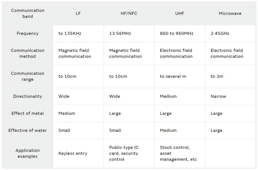
RFID consists of four frequency bands, the LF band, HF band, UHF band, and microwave band. Among the four frequency bands, Murata’s RFID uses HF band and UHF band communication. Since international compatibility is guaranteed by the ISO/IEC 18000 series wireless communication standards. Our RFID products are used throughout the world.

LF Band

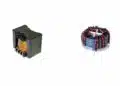
The LF (Low Frequency) band employs an electromagnetic induction method, and has a long history of use compared to other communication bands. One of the example of application is wireless communication in a keyless entry system for an automobile. Although the read range is only several tens of centimeters, it is necessary to use a large number of windings on the antenna, making it difficult to fabricate a thin, compact antenna.
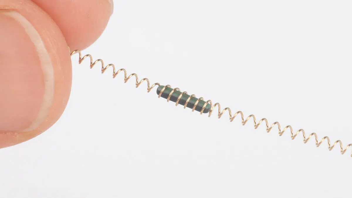
UHF Band

An electronics field type communication method is employed in the UHF (Ultra High-Frequency) band. The frequency range is between 860 and 960MHz, making the UHF band suitable for the applications that requires the communication distance of several meters to read multiple sets of data simultaneously. Most stock control and automatic inspection is carried out using this frequency band.

HF Band

The HF (High Frequency) band exchanges data using an electromagnetic induction method. Compared to the LF band, the HF band requires much smaller number of windings on the antenna, making it easy to fabricate a thin, compact antenna. As the HF band uses 13.56 MHz, which is a frequency in the short wave band, the communication distance is relatively short. Therefore the HF band is suitable for applications in a proximity area, such as those in which persons and items are validated in a 1-to-1 ratio. An NFC (Near Field Communication) device, which is applied for electronic money such as transportation IC card, also uses HF band RFID.

Microwave Band

The microwave band uses the frequency of 2.45GHz, which belongs to the UHF band. Since this band includes the ISM band, which is also used by microwave ovens and wireless LAN (Wi-Fi), there are concerns about radio wave interference. It is therefore necessary to take preventive measures. Also the communication distance is only 2 to 3 meters which is much shorter than that of the band between 860 to 960 MHz.

Table 1. RFID Frequency Bands

Principle of RFID communication

Basically, RFID communication is performed when battery-free passive tag reflects carrier waves sent from the reader/writer.

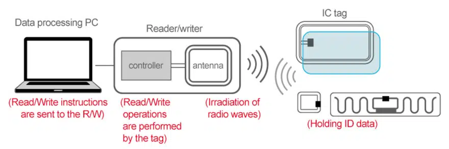
Flow of communication

  1. The reader/writer transmit radio waves.
  2. The antenna inside the IC tag receives radio waves from the reader/writer.
  3. Electric current flows through the IC, converting the data in the chip into signals.
  4. Signals are transmitted from the antenna which is electrode-printed on the IC tag.
  5. The antenna in the reader/writer receives signals returned from the IC tag.
  6. Data is processed by PC via the reader/writer controller
Figure 1. Principle of RFID communication

Related video: What is RFID? How RFID works? RFID Explained in Detail (passive-components.eu)

Related

Source: Murata

Recent Posts

Percolation Phenomenon: Degradation of Molded Power Inductors in DC/DC Converters

21.10.2025
4

Murata Integrates Component Models into Cadence EDA Tools

21.10.2025
10

Bourns Releases High Inductance Common Mode Choke

16.10.2025
16

High Energy Density Polymer Film Capacitors via Molecular and Interfacial Design

15.10.2025
25

Bourns Releases High Clearance and Creepage 1500VDC Power Transformer

15.10.2025
22

YAGEO Unveils Compact 3.6kW LLC Transformer for OBC EV Charging

13.10.2025
134

Over-Voltage Protection Clippers, Clampers, Snubbers, DC Restorers

13.10.2025
29

Silicon Capacitors Market: Shaping the Foundation for Next-Gen Miniaturization Electronics

10.10.2025
66

YAGEO Releases Compact Coupled Inductors for High-Density VR Designs

9.10.2025
28

Enhancing Energy Density in Nanocomposite Dielectric Capacitors

9.10.2025
36

Upcoming Events

Oct 20
October 20 - October 23

Digital WE Days 2025 – Virtual Conference

Oct 21
October 21 @ 12:00 - October 23 @ 14:15 EDT

Space and Military Standards for Hybrids and RF Microwave Modules

Oct 28
8:00 - 15:00 CET

Power Up Your Design: SN6507 and the Ready-to-Use Development Kit

View Calendar

Popular Posts

  • Buck Converter Design and Calculation

    0 shares
    Share 0 Tweet 0
  • Boost Converter Design and Calculation

    0 shares
    Share 0 Tweet 0
  • Flyback Converter Design and Calculation

    0 shares
    Share 0 Tweet 0
  • LLC Resonant Converter Design and Calculation

    0 shares
    Share 0 Tweet 0
  • Ripple Current and its Effects on the Performance of Capacitors

    3 shares
    Share 3 Tweet 0
  • What is a Dielectric Constant and DF of Plastic Materials?

    4 shares
    Share 4 Tweet 0
  • SEPIC Converter Design and Calculation

    0 shares
    Share 0 Tweet 0
  • MLCC and Ceramic Capacitors

    0 shares
    Share 0 Tweet 0
  • Dual Active Bridge (DAB) Topology

    0 shares
    Share 0 Tweet 0
  • Flying Capacitors

    0 shares
    Share 0 Tweet 0

Newsletter Subscription


Passive Components Blog

© EPCI - Leading Passive Components Educational and Information Site

  • Home
  • Privacy Policy
  • EPCI Membership & Advertisement
  • About

No Result
View All Result
  • Home
  • Knowledge Blog
  • PCNS

© EPCI - Leading Passive Components Educational and Information Site

This website uses cookies. By continuing to use this website you are giving consent to cookies being used. Visit our Privacy and Cookie Policy.
Go to mobile version