


The new released APCA7045 ferrite shielded power inductors from YAGEO Group target modern high‑current DC‑DC converters and embedded power rails where designers must balance power density, efficiency, EMI, and thermal reliability in constrained PCB space.
With automotive‑grade options and operation up to 155 °C, the power inductor series is positioned for long‑life use in demanding automotive, industrial, and communication power stages.
Key features and benefits
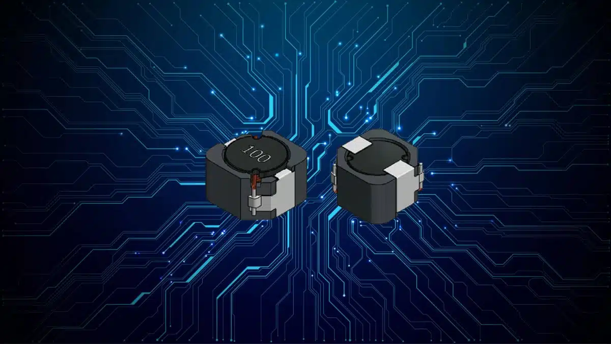
The APCA7045 belongs to YAGEO’s Ferrite Shield Inductors family, designed specifically for compact, high‑current power conversion. The construction combines a ferrite drum core with a ferrite ring shield to achieve stable inductance under DC bias and reduced EMI.
Core construction and magnetic design
- Ferrite NiZn / MnZn drum core
- Supports high inductance stability under DC bias, helping maintain target inductance even as load current increases.
- Reduces the risk of converter instability or loss of control margin at high output currents.
- Ferrite ring core shield structure
- Minimizes magnetic flux leakage, making layout easier in dense PCBs and helping to meet EMI limits.
- Reduces coupling into nearby sensitive signal traces or RF sections.
Typical applications
The APCA7045 is targeted at a wide spectrum of DC‑DC and power rail applications where stable inductance, controlled EMI, and high operating temperature are crucial:
- Buck and boost converters in point‑of‑load (POL) supplies.
- Power modules and adapters, including compact on‑board DC‑DC stages.
- Embedded power rails in complex digital and mixed‑signal systems.
In these circuits, the inductor’s stable inductance under DC bias helps maintain the designed ripple current, switching frequency behavior, and loop stability over the full load range.
End equipment segments:
- Automotive electronics
- Body electronics and comfort systems
- Infotainment and head‑units
- ADAS and other safety‑relevant power rails
- Industrial systems
- Factory automation and motion control
- Programmable logic controllers and I/O modules
- Industrial power supplies and DC bus conditioning
- Communications and networking
- Base stations and remote radio units
- Network switches, routers, and access equipment
- Power conditioning on telecom boards
- Consumer electronics
- High‑density adapters and chargers
- Set‑top boxes, smart home gateways, and STB‑style platforms
- Medical devices
- Where stable inductance and controlled EMI support high‑reliability low‑noise power rails (subject to system‑level regulatory requirements).
In any of these segments, the AEC‑Q200 qualification (for automotive‑grade variants) simplifies reuse across vehicle and industrial projects with similar reliability requirements.
Technical highlights
The table below summarizes key technical attributes for the APCA7045 and the wider APCA family:
| Parameter | APCA7045 / APCA series (typical) |
|---|---|
| Package size range | 6 × 6 × 4.5 mm to 12 × 12 × 8 mm |
| APCA7045 nominal size | 7.0 × 7.0 × 4.5 mm |
| Inductance range | ~1 µH to 470 µH (APCA7045), up to ~1000 µH in family |
| Inductance tolerance | ±20 %, ±30 % |
| DC resistance (RDC) | ~0.0117 Ω to 1.56 Ω |
| Saturation current (Isat) | Up to ~6.5 A |
| RMS current (Irms) | Up to ~4.8 A |
| Breakdown voltage (BDV) | Up to ~1000 V |
| Operating temperature | –55 °C to +150 °C / +155 °C (automotive‑grade variants) |
| Qualification | AEC‑Q200 (automotive‑grade versions) |
All detailed limits and derating behavior should be verified according to the manufacturer datasheet of the specific part number.
What these specs mean in practice
- Inductance range and tolerance
A wide L range enables use as both output inductors in low‑voltage buck stages (lower µH values with higher current) and in input filters or higher‑voltage rails (higher µH values with lower current). The ±20–30 % tolerance is standard for power inductors and should be considered in worst‑case loop stability calculations. - RDC and current ratings (Isat, Irms)
Low RDC directly reduces conduction losses, improving converter efficiency and lowering self‑heating. Isat defines the current at which inductance drops below a specified fraction of its nominal value; exceeding this can increase ripple and potentially stress switching devices. Irms indicates the maximum continuous current that the component can handle thermally without exceeding its temperature rise limit. - High BDV and wide temperature range
A BDV up to about 1000 V allows use in higher‑voltage nodes, for example on primary‑side filters of isolated converters or in HV auxiliary supplies, when supported by the detailed creepage/clearance data in the datasheet. The –55 °C to +155 °C temperature range supports deployment in under‑hood automotive environments or sealed industrial enclosures. - Ferrite shielded structure
Compared with unshielded inductors, the shielded APCA construction reduces radiated magnetic fields, which helps both with EMI compliance and with minimizing cross‑coupling between adjacent inductors in multi‑phase converters.
Design‑in notes for engineers
When designing APCA7045 inductors into a DC‑DC converter or power module, several practical points can help ensure robust operation and smooth qualification.
Selecting the right inductance and current rating
- Match inductance to converter topology
- In step‑down converters, higher inductance reduces ripple current but increases size and can limit fast transient response.
- In step‑up or SEPIC‑type architectures, inductance is crucial to limit peak switch current and achieving acceptable efficiency.
- Use Isat with realistic worst‑case estimates
- Include transient load steps, input voltage variation, and tolerances of both inductance and control IC parameters when calculating peak inductor current.
- Choose a device where Isat significantly exceeds the worst‑case peak to maintain inductance and avoid unexpected mode changes.
- Compare Irms to thermal design targets
- Evaluate copper losses based on RDC and expected RMS current of the actual waveform.
- Consider local airflow, copper area under the inductor, and nearby hot components when estimating temperature rise.
PCB layout and EMI considerations
- Place the APCA7045 as close as possible to the switching device and output capacitors to minimize loop area.
- Use wide copper pours for inductor connections to reduce resistive losses and help with heat spreading.
- Even with the ferrite shield structure, care should be taken to avoid routing sensitive analog or RF traces directly underneath or adjacent to the inductor.
- For multi‑phase or multi‑rail designs, the shielded construction helps reduce coupling between inductors, but inter‑phase spacing and orientation still matter; prototype measurements are recommended.
Thermal management and reliability
- For automotive and industrial projects, consider derating curves in the datasheet and perform thermal simulations or measurements at maximum ambient and load conditions.
- Verify performance over the full –55 °C to +155 °C range where applicable, especially in applications with frequent thermal cycling.
- For AEC‑Q200‑relevant designs, ensure that the inductor is included in the reliability test plan together with other passive components.
Source
This article is based on information provided by YAGEO Group for the APCA Series Power Inductors, specifically the APCA7045 ferrite shielded inductor series for automotive and industrial power designs, complemented by the official product brief and related online resources from the manufacturer.


