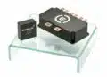


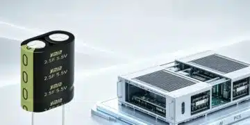

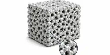


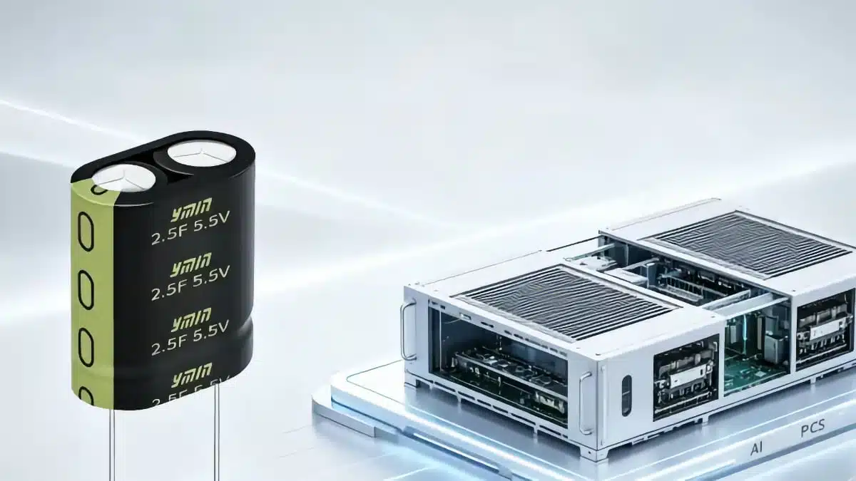
YMIN introduces SDF square supercapacitors, which serve as an ideal solution to provide a localized, ultra-low-ESR energy buffer layer directly at the AI PCS (Power Conversion System) bus. This enhancement improves transient performance and power density for AI server and data center designs.
High‑power AI servers are driving millisecond‑scale load steps that can easily exceed several times the rated power of the power conversion system. In these conditions, traditional buffering with electrolytic or film capacitors struggles to maintain bus stability without oversizing the entire PCS.
Key features and benefits
- Ultra‑low ESR for bus stability
ESR specified below 0.8 mΩ reduces the voltage drop associated with fast current steps and limits self‑heating during high di/dt events. - High pulse current capability
The recommended 3.0 V, 330 F SDF device supports up to 360 A charge and discharge current in the millisecond range, matching typical AI GPU load transients in the 200 ms to 1 s window. - Square form factor for higher power density
The 30 × 20 × 55 mm square package reduces volume by about 30–40% and weight by about 20–30% compared with cylindrical supercapacitors of similar performance, which eases mechanical integration in dense PCS modules. - Wide operating temperature range
Operation from −40 °C to 70 °C allows use in data‑center environments with elevated inlet temperatures and in infrastructure deployed in less controlled ambient conditions. - Long cycle life
A specified cycle life of 500 000 cycles supports 24/7 high‑frequency charge/discharge operation typical of AI workloads and grid‑connected PCS assets. - System‑level cost and size reduction
By absorbing transient peaks locally, the SDF buffer lets designers reduce peak redundancy in upstream UPS/HVDC, rectifier stages, bus capacitors and power devices, which can shrink system size, weight and cooling costs.
Typical applications
SDF square supercapacitors are positioned as transient buffer elements in power conversion systems where load steps are both large and fast:
- AI server and data‑center PCS DC bus buffering to stabilize GPU/CPU supply rails during rapid load ramps.
- UPS/HVDC front‑end “peak shaving and valley filling” to decouple short‑term load surges from upstream power infrastructure.
- GPU cluster power distribution shelves where multiple accelerators switch states in a correlated way, causing millisecond‑scale bus disturbances.
- High‑density modular PCS frames where cylindrical supercapacitors are difficult to place close to the load due to size and height constraints.
In practice, these supercapacitors sit in parallel with the DC bus, often on the same board or sub‑rack as the high‑current GPU power stages, providing a local energy reservoir that can be accessed with minimal parasitic inductance.
Technical highlights
The press release highlights one recommended SDF configuration as a reference point for design‑in.
SDF supercapacitor specifications
| Parameter | Value / description |
|---|---|
| Capacitance | 330 F (single cell) |
| Rated voltage | 3.0 V |
| ESR (typical / max) | < 0.8 mΩ |
| Max charge/discharge current | Up to 360 A (millisecond‑level pulses) |
| Package type | Square supercapacitor |
| Package dimensions | 30 × 20 × 55 mm |
| Operating temperature | −40 °C to 70 °C |
| Cycle life | 500 000 cycles |
According to the manufacturer, the square form factor enables better use of board and rack volume compared to equivalent cylindrical cans, especially when lining up multiple devices along the PCS busbar or power board edge. The specified ESR combined with high capacitance and short interconnects makes SDF devices suitable for limiting voltage sag and overshoot when AI accelerators ramp current within a few hundred microseconds to several milliseconds.
How SDF buffers improve AI PCS behavior
In AI server racks, a single GPU can exceed 700 W and full clusters can exhibit load jumps that are several times the rated steady‑state power of the PCS. If only traditional electrolytic or film capacitors are used, the buffer’s ESR and limited dynamic response can cause bus voltage dips or overshoots that risk GPU or CPU resets, and the usual remedy is to over‑dimension the entire power chain.
The SDF series addresses three pain points cited by YMIN:
- Insufficient bus stability under high di/dt load steps when buffer ESR is too high.
- Excessive system redundancy caused by oversizing bus capacitors, rectifiers and UPS/HVDC stages to cover short transients.
- Poor adaptability of conventional aluminum electrolytic, film and cylindrical supercapacitors in terms of response speed, form factor and mass.
By moving a low‑ESR, high‑capacitance energy buffer physically close to the GPU power stages, designers reduce parasitic inductance in the current path and keep the dynamic support where it is most effective. This allows upstream converters to be sized closer to average or moderately elevated power instead of worst‑case instantaneous peaks, which can yield meaningful savings in magnetic components, semiconductor ratings and thermal design.
Design‑in notes for engineers
When evaluating SDF square supercapacitors against existing designs, power and hardware engineers can use the following practical guidelines:
- Place SDF devices as close as possible to the GPU/CPU DC bus.
Short copper planes or busbars minimize parasitic inductance and ensure the ultra‑low ESR of the device actually translates into effective voltage stabilization. - Dimension the number of cells for both energy and peak current.
The 330 F / 3.0 V rating and 360 A pulse capability provide a starting point, but total required capacitance depends on the allowed bus voltage deviation, load profile and desired buffer time window. - Coordinate protection and control.
Ensure that PCS control loops, current limiting and fault protection schemes account for the strong transient support provided by the supercapacitor so that the upstream converter does not react unnecessarily aggressively to short‑term disturbances. - Check thermal design under repeated pulses.
Although ESR is low, repeated high‑current pulses cause losses; verify that mounting, airflow and ambient conditions keep the device within its −40 °C to 70 °C rating for the actual mission profile. - Compare square vs cylindrical options at system level.
Rather than only matching capacitance, consider board area, clearance/heights, mass and mechanical fixation; the SDF square package can simplify layout in 1U/2U servers and blade‑style power modules. - Plan for lifecycle and serviceability.
With a 500 000‑cycle specification, SDF devices are suited for long‑term deployment, but service intervals and monitoring (for example, ESR or capacity drift) should still be defined for critical installations.
For new AI or data‑center projects, involving the manufacturer’s FAE team early can help optimize the number of devices, their configuration, and their integration with existing UPS/HVDC and PCS architectures.
Source
This article is based on the manufacturer’s press release and related information published by Shanghai YMIN Electronics about the SDF series square supercapacitors for AI server and data‑center PCS applications.