Passive Components Blog
No Result
View All Result
  • Home
  • NewsFilter
    • All
    • Aerospace & Defence
    • Antenna
    • Applications
    • Automotive
    • Capacitors
    • Circuit Protection Devices
    • electro-mechanical news
    • Filters
    • Fuses
    • Inductors
    • Industrial
    • Integrated Passives
    • inter-connect news
    • Market & Supply Chain
    • Market Insights
    • Medical
    • Modelling and Simulation
    • New Materials & Supply
    • New Technologies
    • Non-linear Passives
    • Oscillators
    • Passive Sensors News
    • Resistors
    • RF & Microwave
    • Telecommunication
    • Weekly Digest

    Bourns Releases High Current Metal Alloy-based, Multilayer Power Chip Inductors

    Smiths Interconnect Extends Space-Qualified, High-Reliability Fixed Chip Attenuators 

    Samtec Expands Offering of Slim, High-Density HD Array Connectors

    Bourns Unveils High-Precision Wirewound Resistor with Long-Term Stability

    Common Mode Chokes Selection for RF Circuits in Next-Generation Communication Systems

    Capacitor Self-balancing in a Flying-Capacitor Buck Converter

    Littelfuse Acquires Basler Electric Enhancing High-Growth Industrial Market

    DigiKey Grows Inventory with Over 31K New Stocking Parts in Q3 2025

    Murata Expands Automotive Metal Frame Y2/X1 Safety MLCC Capacitors to 500V

    Trending Tags

    • Ripple Current
    • RF
    • Leakage Current
    • Tantalum vs Ceramic
    • Snubber
    • Low ESR
    • Feedthrough
    • Derating
    • Dielectric Constant
    • New Products
    • Market Reports
  • VideoFilter
    • All
    • Antenna videos
    • Capacitor videos
    • Circuit Protection Video
    • Filter videos
    • Fuse videos
    • Inductor videos
    • Inter-Connect Video
    • Non-linear passives videos
    • Oscillator videos
    • Passive sensors videos
    • Resistor videos

    Common Mode Chokes Selection for RF Circuits in Next-Generation Communication Systems

    Capacitor Self-balancing in a Flying-Capacitor Buck Converter

    How to Select Ferrite Bead for Filtering in Buck Boost Converter

    Power Inductors Future: Minimal Losses and Compact Designs

    Percolation Phenomenon: Degradation of Molded Power Inductors in DC/DC Converters

    Connector PCB Design Challenges

    Efficient Power Converters: Duty Cycle vs Conduction Losses

    Ripple Steering in Coupled Inductors: SEPIC Case

    SEPIC Converter with Coupled and Uncoupled Inductors

    Trending Tags

    • Capacitors explained
    • Inductors explained
    • Resistors explained
    • Filters explained
    • Application Video Guidelines
    • EMC
    • New Products
    • Ripple Current
    • Simulation
    • Tantalum vs Ceramic
  • Knowledge Blog
  • Suppliers
    • Who is Who
  • PCNS
    • PCNS 2025
    • PCNS 2023
    • PCNS 2021
    • PCNS 2019
    • PCNS 2017
  • Events
No Result
View All Result
Passive Components Blog
No Result
View All Result

Impact of Low Temperature on Aluminum Electrolytic Capacitors

28.6.2022
Reading Time: 4 mins read
A A

The article explains impact of low temperature to behaviour of aluminium electrolytic capacitors.

Construction of Aluminum Electrolytic Capacitors

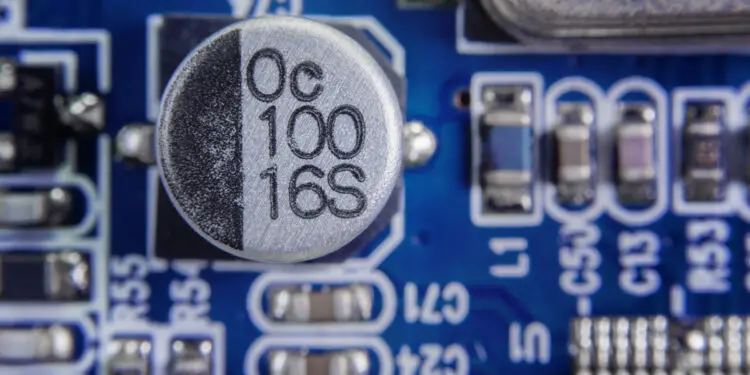
Life all other capacitors, an aluminum electrolytic capacitor comprises of two layers of a conductive material separated by a layer of a dielectric material. An aluminum foil of extremely high purity is used as the anode while a conductive liquid (electrolyte) is used as the cathode. The two aluminum foils of an aluminum electrolytic capacitor provide a large contact area required to allow current to pass to the conductive operating electrolyte. To achieve high capacitance values, the effective contact area of the anode is usually enlarged by electrochemical etching. The type and degree of etching is determined by the desired effective contact area.

RelatedPosts

Bourns Releases High Current Metal Alloy-based, Multilayer Power Chip Inductors

Smiths Interconnect Extends Space-Qualified, High-Reliability Fixed Chip Attenuators 

Samtec Expands Offering of Slim, High-Density HD Array Connectors

An aluminum electrolytic capacitor utilizes an aluminum oxide layer (Al2O3) as the dielectric, allowing production of high capacitance components with very thin layers of dielectric material, often less than 1 µm in thicknesses. This thin dielectric layer in conjunction with the large contact area of the etched anode, means that aluminum electrolytic capacitors offer a higher capacitance per unit area than other dielectric families.

Low Temperature Characteristics of Aluminum Electrolytic Capacitors
Various parameters of aluminum electrolytic capacitors, including operating temperatures and electrical ratings, are greatly influenced by the characteristics of the electrolyte. The properties of the liquid electrolyte that are considerably affected by temperature variations include electrical conductivity and viscosity. The electrical conductivity of the electrolyte increases with an increase in temperature and reduces with a decrease in temperature. Temperature variations have more effect on the characteristics of aluminum electrolytic capacitors than on other types of capacitors. Some of the functional parameters for aluminum electrolytic capacitors that are considerably affected by changes in temperature include capacitance, equivalent series resistance (ESR), tangent delta, leakage current, and impedance.

Capacitance
Temperature changes have significant effects on the capacitance of an aluminum electrolytic capacitor. As the temperature of the electrolyte decreases, its viscosity increases resulting in a reduced electrical conductivity. Therefore, the capacitance of aluminum electrolytic capacitors reduces with a decrease in temperature. At low frequencies, the relationship between temperature and capacitance of aluminum electrolytic capacitors is nearly linear. When operating at -400C, low-voltage aluminum electrolytic capacitors with a low temperature rating of -550C exhibit a capacitance loss of between -10% and -20%. Capacitance loss for high-voltage capacitors can be up to 40%. When operating at the low-temperature limit, the capacitance of aluminum electrolytic capacitors with a low temperature rating of -550C declines by less than 20%.

Equivalent Series Resistance (ESR)
The resistive component of an equivalent series circuit of a capacitor is referred to as the equivalent series resistance (ESR). The ESR of aluminum electrolytic capacitors is considerably affected by variations in temperature and frequency.  In wet aluminum electrolytic capacitors, drastic changes in capacitance are observed when temperature drops. The changes in capacitance are mainly due to the effect of temperature variation on the electrolyte, rather than on the dielectric. The resistivity of the electrolyte increases with a decrease in temperature. For instance, when the temperature drops from 250C to -550C, the resistivity of the electrolyte can increase by a factor of about 100, resulting in a considerable increase in ESR. In wet aluminum capacitors, dramatic changes in ESR are observed as the temperature decreases. For an aluminum electrolytic capacitor operating at the low-temperature limit, the ESR is more than 10 times. If a capacitor with a low-temperature rating of -200C is operated at -400C, its equivalent series resistance can increase by more than a factor of two.

Leakage Current
The leakage current of an electrolytic capacitor is primarily dependent on the characteristics of the dielectric material. Crystal defects, cracks, stress, and installation-related damages are some of the main causes of leakage current. Although the value of leakage current can be decreased by minimizing these defects, it cannot be fully eliminated.  The key factors that affect leakage current include temperature, time, applied voltage, and the design of a capacitor. The leakage current increases with an increase in temperature and reduces with a decrease in temperature. For aluminum electrolytic capacitors, this functional parameter is usually stable at low temperatures. In addition, the initial leakage current of an aluminum electrolytic capacitor is dependent on storage duration and conditions.

Impedance
The impedance of an aluminum electrolytic capacitor is dependent on frequency and temperature. It comprises capacitive reactance of the capacitor, ohmic and dielectric losses of the foils, electrolyte, and terminals, and inductive reactance of the capacitor windings. The capacitive reactance and the equivalent series resistance depend on both frequency and temperature, while inductive reactance depends on frequency only. The impedance of an aluminum electrolytic capacitor increases with a decrease in temperature. When an aluminum electrolytic capacitor is operating at its low-temperature limit, it impedance increases by up to 10 times.

Dissipation Factor (Tangent of Loss Angle or Tan δ)
Dissipation factor or tangent of loss angle of a capacitor refers to the ratio of equivalent series resistance to capacitive reactance. The dissipation factor of an aluminum electrolytic capacitor is dependent on both temperature and frequency. This parameter increases with a decrease in temperature. When operating at the low-temperature limit, the dissipation factor of an aluminum electrolytic capacitor with a low temperature rating of -550C increases more than 10 times. When the same capacitor is operated at -400C, the parameter increases up to 5 times.

Related

Recent Posts

Common Mode Chokes Selection for RF Circuits in Next-Generation Communication Systems

30.10.2025
6

Capacitor Self-balancing in a Flying-Capacitor Buck Converter

30.10.2025
5

Murata Expands Automotive Metal Frame Y2/X1 Safety MLCC Capacitors to 500V

30.10.2025
13

Exxelia 4-Terminal Safety Capacitors Compliant with NF F 62-102 Railway Standard

27.10.2025
25

Samsung Releases Automotive Molded 2220 1kV C0G MLCC

23.10.2025
43

How to Select Ferrite Bead for Filtering in Buck Boost Converter

23.10.2025
41

VINATech Offers Smallest 100µF Al-Hybrid Capacitor

23.10.2025
41

Power Inductors Future: Minimal Losses and Compact Designs

30.10.2025
49

Percolation Phenomenon: Degradation of Molded Power Inductors in DC/DC Converters

30.10.2025
53

Murata Integrates Component Models into Cadence EDA Tools

21.10.2025
48

Upcoming Events

Nov 4
10:00 - 11:00 PST

Design and Stability Analysis of GaN Power Amplifiers using Advanced Simulation Tools

Nov 4
November 4 @ 12:00 - November 6 @ 14:15 EST

Wirebond Materials, Processes, Reliability and Testing

Nov 6
14:30 - 16:00 CET

Self-healing polymer materials for the next generation of high-temperature power capacitors

View Calendar

Popular Posts

  • Buck Converter Design and Calculation

    0 shares
    Share 0 Tweet 0
  • Boost Converter Design and Calculation

    0 shares
    Share 0 Tweet 0
  • LLC Resonant Converter Design and Calculation

    0 shares
    Share 0 Tweet 0
  • Flyback Converter Design and Calculation

    0 shares
    Share 0 Tweet 0
  • Ripple Current and its Effects on the Performance of Capacitors

    3 shares
    Share 3 Tweet 0
  • MLCC and Ceramic Capacitors

    0 shares
    Share 0 Tweet 0
  • Dual Active Bridge (DAB) Topology

    0 shares
    Share 0 Tweet 0
  • What is a Dielectric Constant and DF of Plastic Materials?

    4 shares
    Share 4 Tweet 0
  • SEPIC Converter Design and Calculation

    0 shares
    Share 0 Tweet 0
  • Flying Capacitors

    0 shares
    Share 0 Tweet 0

Newsletter Subscription


Passive Components Blog

© EPCI - Leading Passive Components Educational and Information Site

  • Home
  • Privacy Policy
  • EPCI Membership & Advertisement
  • About

No Result
View All Result
  • Home
  • Knowledge Blog
  • PCNS

© EPCI - Leading Passive Components Educational and Information Site

This website uses cookies. By continuing to use this website you are giving consent to cookies being used. Visit our Privacy and Cookie Policy.
Go to mobile version