Passive Components Blog
No Result
View All Result
  • Home
  • NewsFilter
    • All
    • Aerospace & Defence
    • Antenna
    • Applications
    • Automotive
    • Capacitors
    • Circuit Protection Devices
    • electro-mechanical news
    • Filters
    • Fuses
    • Inductors
    • Industrial
    • Integrated Passives
    • inter-connect news
    • Market & Supply Chain
    • Market Insights
    • Medical
    • Modelling and Simulation
    • New Materials & Supply
    • New Technologies
    • Non-linear Passives
    • Oscillators
    • Passive Sensors News
    • Resistors
    • RF & Microwave
    • Telecommunication
    • Weekly Digest

    Smiths Interconnect Extends Space-Qualified, High-Reliability Fixed Chip Attenuators 

    Samtec Expands Offering of Slim, High-Density HD Array Connectors

    Bourns Unveils High-Precision Wirewound Resistor with Long-Term Stability

    Common Mode Chokes Selection for RF Circuits in Next-Generation Communication Systems

    Capacitor Self-balancing in a Flying-Capacitor Buck Converter

    Littelfuse Acquires Basler Electric Enhancing High-Growth Industrial Market

    DigiKey Grows Inventory with Over 31K New Stocking Parts in Q3 2025

    Murata Expands Automotive Metal Frame Y2/X1 Safety MLCC Capacitors to 500V

    Source: Semiconductor Intelligence

    October 25 Electronics Production: U.S. vs. Global Changes

    Trending Tags

    • Ripple Current
    • RF
    • Leakage Current
    • Tantalum vs Ceramic
    • Snubber
    • Low ESR
    • Feedthrough
    • Derating
    • Dielectric Constant
    • New Products
    • Market Reports
  • VideoFilter
    • All
    • Antenna videos
    • Capacitor videos
    • Circuit Protection Video
    • Filter videos
    • Fuse videos
    • Inductor videos
    • Inter-Connect Video
    • Non-linear passives videos
    • Oscillator videos
    • Passive sensors videos
    • Resistor videos

    Common Mode Chokes Selection for RF Circuits in Next-Generation Communication Systems

    Capacitor Self-balancing in a Flying-Capacitor Buck Converter

    How to Select Ferrite Bead for Filtering in Buck Boost Converter

    Power Inductors Future: Minimal Losses and Compact Designs

    Percolation Phenomenon: Degradation of Molded Power Inductors in DC/DC Converters

    Connector PCB Design Challenges

    Efficient Power Converters: Duty Cycle vs Conduction Losses

    Ripple Steering in Coupled Inductors: SEPIC Case

    SEPIC Converter with Coupled and Uncoupled Inductors

    Trending Tags

    • Capacitors explained
    • Inductors explained
    • Resistors explained
    • Filters explained
    • Application Video Guidelines
    • EMC
    • New Products
    • Ripple Current
    • Simulation
    • Tantalum vs Ceramic
  • Knowledge Blog
  • Suppliers
    • Who is Who
  • PCNS
    • PCNS 2025
    • PCNS 2023
    • PCNS 2021
    • PCNS 2019
    • PCNS 2017
  • Events
No Result
View All Result
Passive Components Blog
No Result
View All Result

A Simple Method for a Capacitor’s ESR Measurement

27.11.2019
Reading Time: 6 mins read
A A

source: Power Electronics article

Farzin Asadi, Nurettin Abut | Sep 07, 2017, Accurate modeling of power electronic converters, i.e., obtaining control to output transfer function, must include series resistance of capacitors and inductors. A simple method allows measurement of a capacitor’s Equivalent Series Resistance (ESR).

RelatedPosts

KEMET Design it Day: Capacitors and Inductors Selection Guide for Decoupling And Filtering

How to determine and measure MLCC ripple current and ESR

Degradation of ESR in Polymer Tantalum Capacitors during High Temperature Storage BEST PAPER AWARD

 Capacitors are classified according to their dielectric’s type. Electrolytic capacitors are popular in power electronic circuits, due to their high volumetric efficiency and excellent price performance ratio.[1] Unfortunately, their characteristics change with operating frequency, whereas an ideal capacitor’s impedance decreases with frequency. But, in the real world this is not seen in the laboratory. Increasing frequency up to a certain point leads to the expected impedance reduction but increasing frequency causes the impedance to increase, i.e., it acts like a resonance circuit. To model the behavior of an actual capacitor requires the addition of extra elements to the capacitor model. ESR is actually the resistance that a capacitor shows in the border between capacitor-like behavior and inductor-like behavior, i.e., resistance at the resonance frequency.

When modeling the dynamic behavior of power converters, ESR is important value because it predicts the output ripple of the converter as well as predicting capacitor lifetime.[2] Power dissipated in ESR causes the capacitor’s temperature to increase and its capacitance and lifetime to decrease.

A simple and direct method for measuring ESR is proposed in [3], in which the ESR is determined directly by the ratio of the capacitor’s ripple voltage to ripple current. But the implementation is quite expensive and troublesome. To determine ESR using only voltage measurements, Chen et al. [4] suggested that under some specific conditions, the inductor ripple current could be assumed to be constant and hence the output ripple voltage determines the ESR. However, the proposed method is limited and its precision is not high.

 A laboratory method that can be used to determine the intrinsic value of ESR of electrolytic capacitors was proposed in [5]. However, the method is expensive to implement.

Here, we present a simple measurement technique for the determination of capacitor ESR.

Proposed Method:

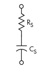
Assume a model like that shown in Fig. 1, for Capacitor Under Test (CUT):

1. Model of capacitor under test.


This model ignores lead inductance. Suppose that CUT is connected to a sine wave generator with frequency Fg and internal resistance rg, as shown in Fig. 2:

2. CUT connected to a sine wave generator.

The transfer function of this circuit is:

Equation 1, shows the high pass nature of this circuit. Therefore, we can approximate the transfer function as:

Equation 2 is the basis for our capacitor ESR measurement. When the input frequency is high enough we can simplify the input-output relation as algebraic Equation 2. For high frequencies, the circuit acts like an attenuator with the attenuation factor:

Measurement of circuit’s attenuation factor and generator’s internal resistance leads to rc, the capacitor’s ESR:

Instead of using a sine wave excitation, we can use a square wave. This allows us to use a Fourier series to write an equation with levels +Vm and -Vm, and period T:

Where:

A square wave consists of odd harmonics. When fundamental harmonic is high enough, a capacitor acts like short circuit and output voltage is approximately attenuated version of input voltage in steady state. Circuit attenuation in steady state is directly related to capacitor equivalent series resistance, rc , that can be obtained by measuring the circuit’s attenuation factor and using Equation 3.

Simulation Results:

Simulink diagram is shown in Fig. 3:

3. Simulation diagram of circuit in Simulink.

A square wave with amplitude +1 and -1 volt is used as excitation. Signal generator output resistance is taken as 50 Ω, capacitor is 30 μF with 0.8 Ω ESR. Steady-state output waveform is shown in Fig. 4:


4. Steady-state output of circuit.

The calculated attenuation factor of the circuit is:

and CUT’s ESR is calculated as:

Laboratory Results:

A signal generator with nominal 50 Ω output resistance provides the excitation. An output resistance of 47.1 Ω is measured with the aid of a simple voltage divider. Steady state output voltage peak-peak voltage is measured with the aid of a digital scope. Figure 5 shows s sample output.

5. Sample output voltage waveform.

Calculated ESR Values

This simple measurement technique provides accurate results and allows a more precise power converter model.


References

1. Amaral A.M.R., Cardoso A.J.M.: An experimental technique for estimating the ESR and reactance intrinsic values of aluminium electrolytic capacitors. Proc. Instrumentation and Measurement Technology Conf., IMTC 2006, April 2006, pp. 1820–1825.

2. Sankaran V.A., Rees F.L., Avant C.S.: Electrolytic capacitor life testing and prediction. Proc. 32nd Annual Meeting IEEE Industry Applications Society, October 1997, vol. 2, pp. 1058–1065

3. Venet P., Perisse F., El-Husseini M.H., Rojat G.: Realization of a smart electrolytic capacitor circuit, IEEE Ind. Appl. Mag., 2002, 8, (1), pp. 16–20

4. Chen Y.-M., Chou M.-W., Wu H.-C.: Electrolytic capacitor failure prediction of LC filter for switching-mode power converters. Proc. 40th Annual Meeting IEEE Industry Applications Society, October 2005, vol. 2, pp. 1464–1469.

5. Amaral A.M.R., Cardoso A.J.M.: An ESR meter for high frequencies. Proc. Int. Conf. on Power Electronics and Drives Systems, PEDS, 2005, pp. 1628–163

6. D.W. Hart, “Power electronics,” Mc Graw Hill, 2010.

7. N. Mohan,T. M. Undeland , W. P. Robbins, “Power Electronics: Converters, Applications and Design,” John Wiley and Sons, 2002.

8. R.W. Ericson, D. Maksimovic, “Fundamental of power electronics,” Springer, 2001.

9. A.M.R. Amaral, A.J.M Cardoso: “An ESR meter for high frequencies“. Proc. Int. Conf. on Power Electronics and Drives Systems, PEDS, 2005, pp. 1628–1633.

10. R. Chen, J.D.V. Wyk, S. Wang, W.G. Odendaal: Improving the characteristics of integrated EMI filters by embedded conductive layers. IEEE Trans. Power Electron., 2005, pp. 611–619.

11. A.M.R. Amaral, A.J.M Cardoso: An experimental technique for estimating the ESR and reactance intrinsic values of aluminium electrolytic capacitors. Proc. Instrumentation and Measurement Technology Conf., IMTC 2006, April 2006, pp. 1820–1825.

Related

Recent Posts

Capacitor Self-balancing in a Flying-Capacitor Buck Converter

30.10.2025
1

Murata Expands Automotive Metal Frame Y2/X1 Safety MLCC Capacitors to 500V

30.10.2025
3

Exxelia 4-Terminal Safety Capacitors Compliant with NF F 62-102 Railway Standard

27.10.2025
23

Samsung Releases Automotive Molded 2220 1kV C0G MLCC

23.10.2025
42

VINATech Offers Smallest 100µF Al-Hybrid Capacitor

23.10.2025
38

Murata Integrates Component Models into Cadence EDA Tools

21.10.2025
46

High Energy Density Polymer Film Capacitors via Molecular and Interfacial Design

15.10.2025
31

KYOCERA AVX Expands Stacked MLCC Capacitors Offering

14.10.2025
49

Silicon Capacitors Market: Shaping the Foundation for Next-Gen Miniaturization Electronics

10.10.2025
87

Enhancing Energy Density in Nanocomposite Dielectric Capacitors

9.10.2025
44

Upcoming Events

Nov 4
10:00 - 11:00 PST

Design and Stability Analysis of GaN Power Amplifiers using Advanced Simulation Tools

Nov 4
November 4 @ 12:00 - November 6 @ 14:15 EST

Wirebond Materials, Processes, Reliability and Testing

Nov 6
14:30 - 16:00 CET

Self-healing polymer materials for the next generation of high-temperature power capacitors

View Calendar

Popular Posts

  • Buck Converter Design and Calculation

    0 shares
    Share 0 Tweet 0
  • Boost Converter Design and Calculation

    0 shares
    Share 0 Tweet 0
  • Flyback Converter Design and Calculation

    0 shares
    Share 0 Tweet 0
  • LLC Resonant Converter Design and Calculation

    0 shares
    Share 0 Tweet 0
  • Ripple Current and its Effects on the Performance of Capacitors

    3 shares
    Share 3 Tweet 0
  • What is a Dielectric Constant and DF of Plastic Materials?

    4 shares
    Share 4 Tweet 0
  • SEPIC Converter Design and Calculation

    0 shares
    Share 0 Tweet 0
  • Dual Active Bridge (DAB) Topology

    0 shares
    Share 0 Tweet 0
  • MLCC and Ceramic Capacitors

    0 shares
    Share 0 Tweet 0
  • Flying Capacitors

    0 shares
    Share 0 Tweet 0

Newsletter Subscription


Passive Components Blog

© EPCI - Leading Passive Components Educational and Information Site

  • Home
  • Privacy Policy
  • EPCI Membership & Advertisement
  • About

No Result
View All Result
  • Home
  • Knowledge Blog
  • PCNS

© EPCI - Leading Passive Components Educational and Information Site

This website uses cookies. By continuing to use this website you are giving consent to cookies being used. Visit our Privacy and Cookie Policy.
Go to mobile version