


The emergence and future ubiquity of electric vehicles have created one of the most demanding application spaces for capacitors across a wide variety of use cases. From AC charging circuits to high-speed analog sensors, electric vehicles span the gamut of design constraints while also requiring the highest reliability standards in the worst possible environments. John Lee and Simon Cen from AVX Corporation describes use of capacitors in EVs DC/DC converters and advantage of MLCC automotive grade ceramic capacitors there.
Introduction
The emergence and future ubiquity of electric vehicles have created one of the most demanding application spaces for capacitors across a wide variety of use cases. From AC charging circuits to high-speed analog sensors, electric vehicles span the gamut of design constraints while also requiring the highest reliability standards in the worst possible environments. To meet this need, manufacturers are pushing the boundaries of capacitor capability while simultaneously expanding their portfolios with new capacitor technologies.
Today, many capacitor chemistries, structures, and form-factors are available for designing around requirements such as density, size, reliability, and cost, to name a few. As a designer, choosing the right capacitor from this sea of options can make or break a product’s success. One particular circuit stands out in this challenge, both for its importance and routine use: the DC-DC converter.
Electric vehicle dc-dc converters
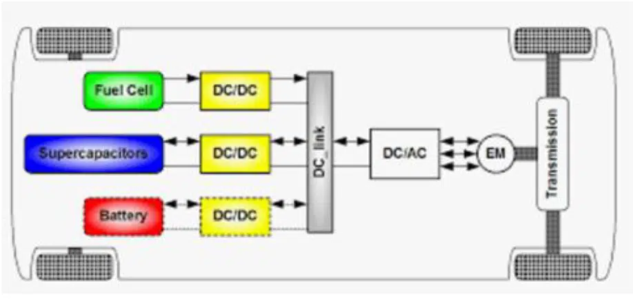
DC-DC converters can be found in nearly everysubsystem of an electric vehicle (EV). Fromhigh power charging and power distributioncircuits to simple USB ports, EVs requirenumerous DC voltages with varying demandson power, temperature, ripple, and the like. Forexample, a block-level EV powertrain is shownin Figure 1 incorporating various high powerDC-DC converters.
While EVs do make extensive use of DC-DC converters, none of them are particularly unusual in their function. The real design challenge stems from the rigorous quality and reliability demands placed on automotive manufacturers by the AECQ-200 qualification standard. This regulatory body ensures automobile safety and reliability by imposing acceptable test limits for electrical stress, moisture resistance, operational lifetime, mechanical shock and vibration, and PCB flexing. The four most common AECQ-200 qualified capacitor technology offerings in the market include the aluminum electrolytic capacitor, the Tantalum capacitor, the film capacitor, and the ceramic capacitor.
The capacitor landscape
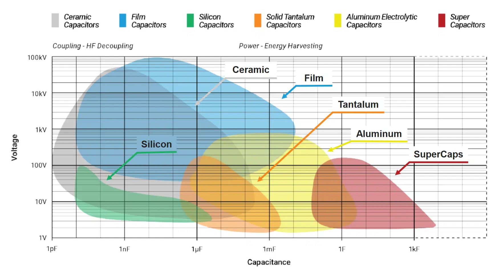
Capacitors can be made using many different structures and materials. Each capacitor technology has inherent limitations in its available capacitance and voltage range. Figure 2 depicts several different capacitor families and how their capacitance and voltage are related.
Additionally, different varieties of capacitors offer characteristics that may be beneficial in performance for a particular application. Aluminum electrolytics have wide voltage and capacitance ratings at attractive price points but suffer from reliability issues due to electrolyte volatilization and leakage. Tantalum devices have excellent electrical stability over a wide temperature range but suffer from lower voltage ratings and potential short circuit failure modes.
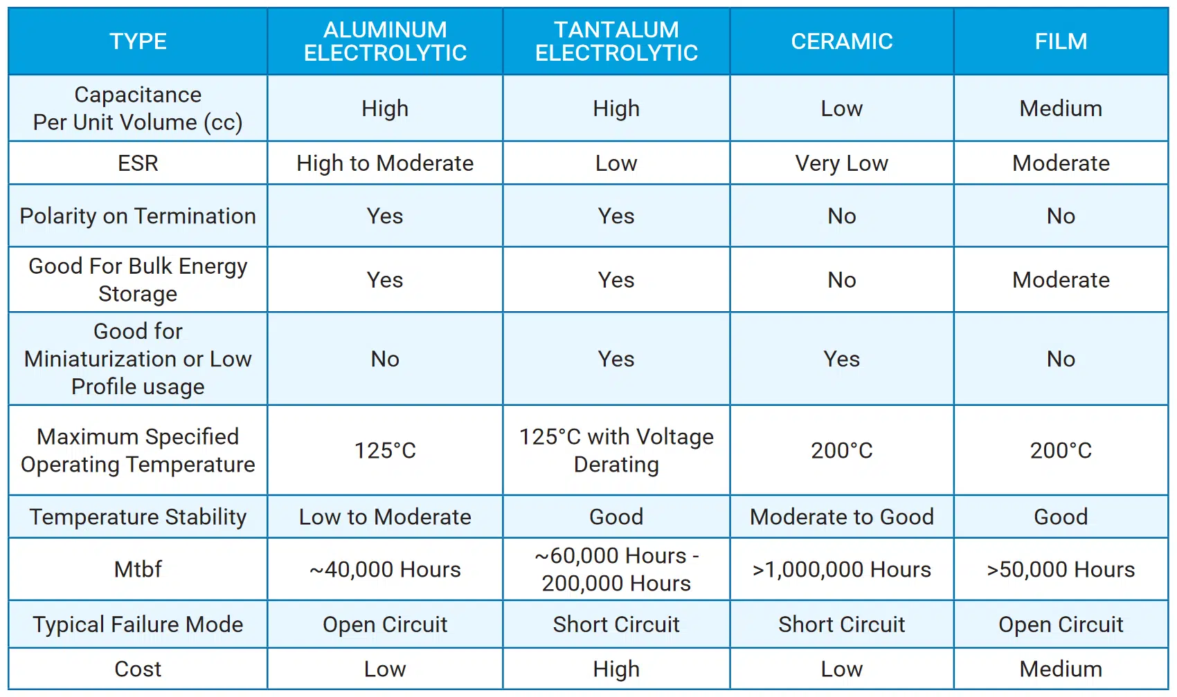
Polymer film capacitors are widely used in industrial circuits due to their excellent inrush current handling capability and high reliability. Still, they may be unsuitable in many automotive applications due to their large form-factor and high relative price. The ceramic capacitor stands out for its wide voltage range and low series resistance (ESR). These characteristics make it particularly well suited in DC-DC converter applications where ESR can be a primary design constraint. Unfortunately, traditional ceramic capacitors suffer from relatively low density and are sensitive to handling damage and PCB flex cracking. Figure 3 summarizes some of these trade-offs in a comparison table.
Multilayer MLCC ceramic capacitors
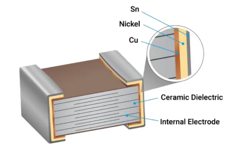
Multilayer Ceramic Capacitors (MLCC) are a type of ceramic capacitor consisting of ceramic dielectric layers printed with electrodes (internal electrodes) and stacked to form the capacitive structure. After high-temperature sintering, a ceramic chip is formed, and the two ends of the chip are sealed with metal layers (external electrodes) to create a monolithic structure. This device topology is shown in figure 4.
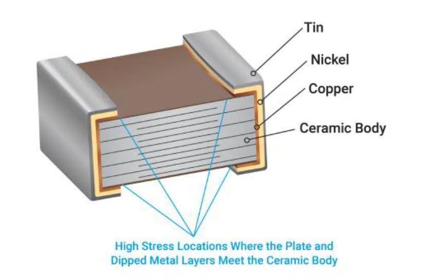
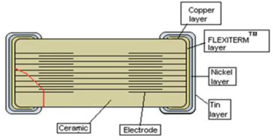
MLCC’s offer high capacitance density and a wide range of voltage tolerance due to the ceramic dielectric’s electrical properties. At the same time, the relative stiffness of ceramic makes it prone to cracking when the underlying PCB flexes. As shown in figure 5, the interface between the external electrode and the ceramic chip results in a high stress (H+) concentration that can quickly lead to component failure.

Manufacturers have developed two strategies to mitigate this cracking mechanism: flexible termination and cascaded electrodes. When flexible termination is added to the outer electrodes, a truly robust capacitor is created. As shown in figure 6, a conductive flexible polymer is included between the outer electrode’s copper and nickel layers. AVX refers to this as “Flexiterm®” technology, and it allows the PCB to flex by a depth of up to 5 mm, compared to the traditional 2-3 mm, with no cracking failure.
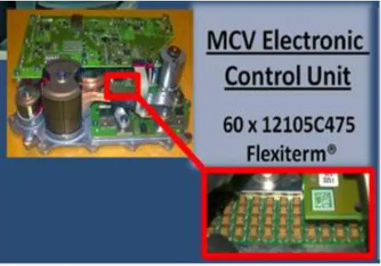
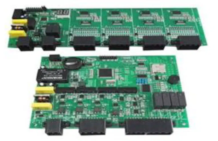
Many automotive customers turn to soft termination for all MLCC usage in their designs to protect against failure from mishandling of circuit boards or devices, reducing their potential field return rate of their products, and boosting their quality reputation. An example MLCC design is shown in figure 7. Multiple soft terminated devices are used in parallel to provide a highly reliable filter capacitance for an automotive DC-DC converter.
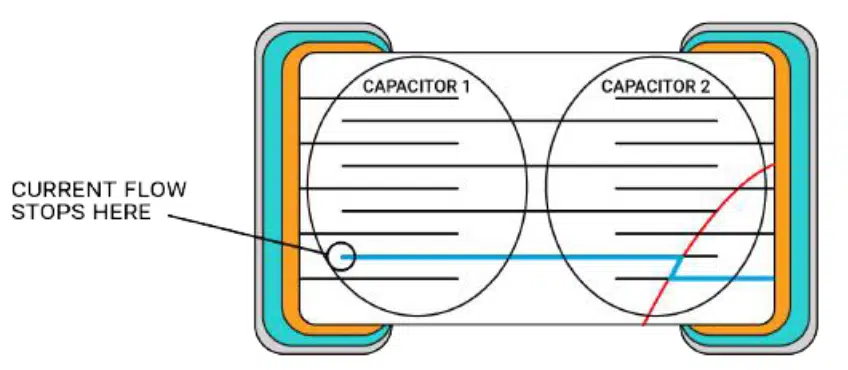
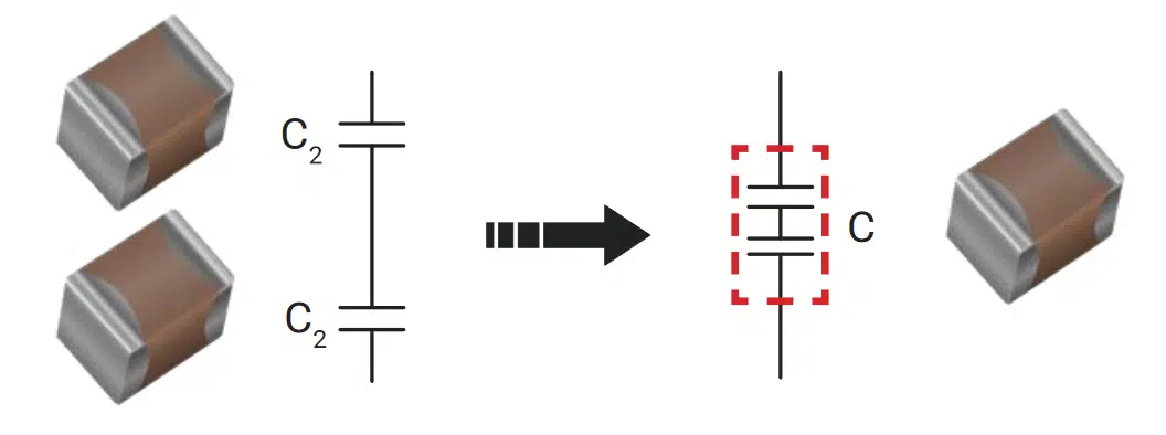
The cascaded electrode design is shown in figure 8, where floating inner electrodes are used to create two capacitors in series (MLCC) effectively. With this cascaded structure, the severity of component failure is reduced because a crack in one part of the ceramic chip does not necessarily render the entire capacitor useless. This structure also increases the capacitor’s overall voltage rating since the potential is distributed between two serial devices.
However, the cascade electrodes or multi-layer serial ceramic capacitors are also prone to mechanically induced damages like cracks caused by excessive board flexure.
To minimize this problem, AVX had incorporated flexible epoxy layer on the termination of these MLCC products, and they are market under the AVX “FlexiSafe®” product series.
Even when the FlexiSafe® capacitor is subjected to excessive board flexure or aggressive vibration well beyond the product’s specification, it will still not affect other capacitors within the same package. The worse-case outcome may result in a mechanical crack on one side of the termination resulting in a short circuit.The “FlexiSafe®” products are probably the world’s safest SMD ceramic capacitors.
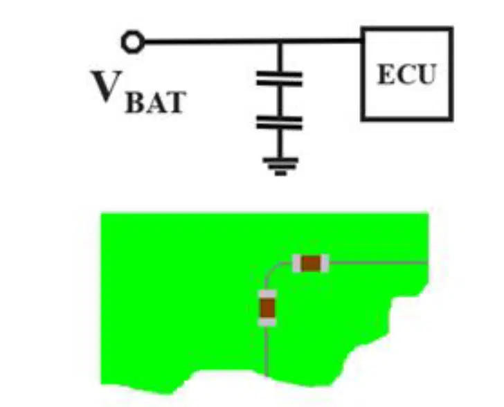
In many automotive OEMs, they have strict PCB design rules for the PAAT (Power Active All the Time), Direct Battery (Terminal 30) connection and many demanding “Fail-Safe” applications by requiring 2 ceramic capacitors in series to be placed physically at 90 degrees to each other.
In the unlikely event that one of the capacitors fails, resulting short circuit, the other capacitor in the series will still work, preventing a system shut down. The reason for putting the ceramic capacitors 90 degrees to each other is prevent cracks on both ceramic capacitors due to board flexure or mishandling issues. Figure 10 shows an example of the PCB layout for such “fail-safe” application.
The major disadvantage of the 2-Capacitors 90 degrees in series design, shown in figure 10, is the board space required to implement the design. With automotive electronics miniaturization, designers are pressed to reduce the board size without compromising with the capacitors’ quality and reliability expectation. The AVX FlexiSafe® products are best fit for such applications and are now widely approved in major automotive OEMs for their “Fail-Safe” applications that previously required the 2 discrete capacitors in series solution.
FlexiSafe® capacitors are widely used in many mission critical and safety-linked automotive applications including ECU, ADAS, BMS, EPS, ESC, etc..
Conclusion
Electric vehicles have created a new landscape of available capacitor technologies to meet automotive quality and reliability standards. One of these technologies — the soft terminated MLCC — stands out as an ideal candidate for automotive DC-DC applications. Even though EVs contain many different types of DC-DC converters, they universally require output filter capacitors with low ESR, high current capability,and wide ranges of voltage rating. The soft terminated MLCC satisfies all of the demands while providing exceptional reliability and affordable prices.