


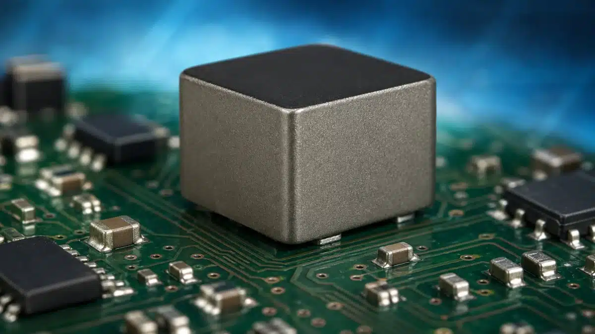
Sumida has introduced the WMT1513T150/DS family of AEC‑Q200 qualified SMD metal inductors aimed at high‑reliability automotive DC/DC converter stages.
These magnetically shielded high current power inductors combine soft saturation behaviour, high rated current and low DCR, making them attractive for space‑constrained power rails in ECUs and other demanding automotive electronics.
Key features and benefits
- AEC‑Q200 qualified for automotive use, simplifying approval in automotive ECUs and helping OEMs and Tier‑1 suppliers align with standard automotive stress and reliability tests.
- Magnetically shielded SMC construction, reducing stray flux and mutual coupling in dense layouts and improving EMC behaviour in multi‑rail power boards.
- Soft saturation characteristic, providing more predictable inductance roll‑off at high current, which helps maintain control loop stability and reduce peak current stress in switching converters.
- High rated current capability, up to several tens of amperes according to the manufacturer datasheet, enabling use on high‑current point‑of‑load rails and core supply lines.
- Low DCR across the range, which directly reduces conduction losses and self‑heating and helps keep efficiency high in DC/DC converters.
- Wide operating temperature range from −55 °C to +150 °C (including self‑heating), suitable for under‑hood or near‑powertrain locations where ambient plus temperature rise can be severe.
- Absolute maximum voltage across the inductor of 50 V, supporting a wide range of input and output combinations in automotive 12 V and 24 V based systems.
Typical applications
The WMT1513T150/DS inductor series is targeted at automotive power stages that require high current and robust environmental performance.
- DC/DC converters in electronic control units (engine, transmission, body and chassis controllers)
- POL regulators for microcontrollers, SoCs and FPGAs within ECUs
- Power supplies for infotainment, ADAS and power distribution modules
- Generic high‑reliability automotive power rails where AEC‑Q200 qualification is mandatory
Sumida explicitly notes that the WMT1513T150/DS devices are not intended for use in airbag or braking system applications, so safety‑critical functions in those domains should rely on components specifically approved for such use cases.
Technical highlights
The family is implemented as a surface‑mount, metal‑composite inductor with magnetic shielding and is offered in multiple inductance values with corresponding DCR and current ratings.
Electrical characteristics overview
Below is a condensed view of the electrical characteristics as given in the manufacturer data:
| Part number | Inductance (µH) ±20% | DCR max (mΩ) | DCR typ (mΩ) | Saturation current max (A) | Saturation current typ (A) | Temp. rise current typ (A) |
|---|---|---|---|---|---|---|
| WMT1513T150DS‑4R7MC | 4.70 | 3.30 | 2.50 | 35.0 | 41.0 | 27.0 |
| WMT1513T150DS‑5R6MC | 5.60 | 3.90 | 3.30 | 31.5 | 37.0 | 24.0 |
| WMT1513T150DS‑6R8MC | 6.80 | 4.40 | 3.70 | 29.0 | 34.0 | 23.0 |
| WMT1513T150DS‑8R2MC | 8.20 | 5.80 | 4.90 | 28.0 | 33.0 | 19.0 |
| WMT1513T150DS‑100MC | 10.00 | 7.00 | 5.50 | 23.5 | 28.0 | 17.5 |
| WMT1513T150DS‑150MC | 15.00 | 7.50 | 6.40 | 21.5 | 25.5 | 16.0 |
| WMT1513T150DS‑220MC | 22.00 | 14.00 | 12.00 | 18.5 | 22.0 | 12.0 |
| WMT1513T150DS‑330MC | 33.00 | 21.00 | 17.00 | 16.0 | 19.0 | 9.0 |
- Inductance tolerance is ±20% across the range, which is typical for power inductors in DC/DC applications.
- As inductance increases, DCR rises and the saturation and temperature‑rise currents decrease, so lower‑value parts are favoured for higher‑current rails.
- The series offers a balance between energy storage, low loss and current capability suitable for multi‑ampere step‑down regulators.
Exact mechanical dimensions, pad layout and further electrical curves (inductance versus current, frequency characteristics, core loss) are available in the manufacturer datasheet and should be consulted during detailed design.
Availability and part numbers
The WMT1513T150/DS is listed as being in series production, which is relevant for long‑term automotive projects where lifecycle and supply risk are key considerations. The family currently includes eight inductance values from 4.7 µH up to 33 µH, each with its own current and resistance profile.
Ordering options
| Inductance group | Part numbers (example) | Typical use case hint |
|---|---|---|
| 4.7–6.8 µH | WMT1513T150DS‑4R7MC / ‑5R6MC / ‑6R8MC | Higher‑current buck stages, low output voltages |
| 8.2–15 µH | WMT1513T150DS‑8R2MC / ‑100MC / ‑150MC | Mid‑current rails, moderate duty cycles |
| 22–33 µH | WMT1513T150DS‑220MC / ‑330MC | Pre‑regulators, noise‑sensitive loads |
For exact reel quantities, packaging format and tolerance options, refer to the official product page and datasheet.
Design‑in notes for engineers
For power designers and layout engineers, the WMT1513T150/DS family provides a straightforward drop‑in option for AEC‑Q200 compliant automotive DC/DC stages, but a few selection and implementation points are worth highlighting.
Electrical selection guidelines
- Select the inductance value based on the converter topology, switching frequency and target ripple current; mid‑range values in this series suit typical automotive buck converters in the hundreds of kilohertz range.
- Ensure the peak inductor current, including transient and start‑up conditions, stays below the specified saturation current with adequate margin to maintain inductance and avoid control loop distortion.
- Use both DCR and temperature‑rise current as thermal design inputs: compute copper losses from DCR and RMS current and verify that the predicted temperature rise keeps the body temperature within the specified −55 °C to +150 °C range.
- Take the 50 V maximum voltage across the inductor into account when designing for higher input voltages or fault scenarios to avoid exceeding insulation and construction limits.
Layout and EMC considerations
- Leverage the magnetically shielded structure by placing the inductor close to the switching FETs and input capacitors to minimise loop area, further improving EMI performance.
- Avoid routing sensitive analog or high‑impedance traces underneath the inductor footprint to reduce the impact of residual fringing fields and switching noise.
- Ensure solid thermal paths through copper planes and vias under the component to dissipate losses and reduce hot spots, especially at high current levels.
Automotive qualification and reliability
- AEC‑Q200 qualification helps streamline component approval, but system‑level validation (thermal cycling, vibration, humidity) is still necessary for the final ECU design.
- Since these parts are not intended for airbag or braking applications, ensure that safety‑critical systems follow the manufacturer’s restrictions and that any such functions use components approved specifically for those use cases.
- For long‑term supply programmes, confirm with Sumida and distribution channels that the specific WMT1513T150/DS variants are planned for continuous series production.
Source
This article is based on information from the official Sumida Corporation product news and associated product documentation for the WMT1513T150/DS SMD metal inductor series, complemented with general application guidance for automotive DC/DC converter design.


