Passive Components Blog
No Result
View All Result
  • Home
  • NewsFilter
    • All
    • Aerospace & Defence
    • Antenna
    • Applications
    • Automotive
    • Capacitors
    • Circuit Protection Devices
    • electro-mechanical news
    • Filters
    • Fuses
    • Inductors
    • Industrial
    • Integrated Passives
    • inter-connect news
    • Market & Supply Chain
    • Market Insights
    • Medical
    • Modelling and Simulation
    • New Materials & Supply
    • New Technologies
    • Non-linear Passives
    • Oscillators
    • Passive Sensors News
    • Resistors
    • RF & Microwave
    • Telecommunication
    • Weekly Digest

    Binder Extends NCC Circular Connectors for Harsh Environments

    Standard vs Planar LLC transformers Comparison for Battery Chargers

    Würth Elektronik and Grinn Launch Edge AI Cooperation

    Bourns Expanded Semi-Shielded Low Profile Automotive Power Inductor

    Peak Nano to Develop Fusion Grade High Energy Film Capacitors

    Murata New Vibration Sensor Targets High‑Frequency Predictive Maintenance

    Kyocera Releases 30fs Jitter Differential Clock Oscillator

    Panasonic Expands Automotive PP Film Capacitors Voltage Range

    Panasonic Extends Automotive Power Inductor Line

    Trending Tags

    • Ripple Current
    • RF
    • Leakage Current
    • Tantalum vs Ceramic
    • Snubber
    • Low ESR
    • Feedthrough
    • Derating
    • Dielectric Constant
    • New Products
    • Market Reports
  • VideoFilter
    • All
    • Antenna videos
    • Capacitor videos
    • Circuit Protection Video
    • Filter videos
    • Fuse videos
    • Inductor videos
    • Inter-Connect Video
    • Non-linear passives videos
    • Oscillator videos
    • Passive sensors videos
    • Resistor videos

    Standard vs Planar LLC transformers Comparison for Battery Chargers

    How Modern Tools Model Magnetic Components for Power Electronics

    Advanced Loss Modeling for Planar Magnetics in the Frenetic Planar Tool

    2026 Power Magnetics Design Trends: Flyback, DAB and Planar

    Enabling Software‑Defined Vehicle Architectures: Automotive Ethernet and Zonal Smart Power

    Calculating Resistance Value of a Flyback RC Snubber 

    One‑Pulse Characterization of Nonlinear Power Inductors

    Thermistor Linearization Challenges

    Coaxial Connectors and How to Connect with PCB

    Trending Tags

    • Capacitors explained
    • Inductors explained
    • Resistors explained
    • Filters explained
    • Application Video Guidelines
    • EMC
    • New Products
    • Ripple Current
    • Simulation
    • Tantalum vs Ceramic
  • Knowledge Blog
  • DossiersNew
  • Suppliers
    • Who is Who
  • PCNS
    • PCNS 2025
    • PCNS 2023
    • PCNS 2021
    • PCNS 2019
    • PCNS 2017
  • Events
No Result
View All Result
Passive Components Blog
No Result
View All Result

Cavity Resonator Filters Basics

4.1.2023
Reading Time: 5 mins read
A A

This blog article from Knowles Precision Devices explains cavity filter basics and its advantages in high performance under high power.

As discussed in previous ceramic coaxial resonator filter blog post, resonators are the building blocks used to create filters. 

RelatedPosts

Knowles Doubles Capacitance of its Class I Ceramic C0G Capacitors

3-Phase EMI Filter Design, Simulation, Calculation and Test

Knowles Releases High Q Non-Magnetic X7R MLCCs for Medical Imaging

We published a blog post Resonators as Microwave Devices that discussed two different types of resonators – coaxial ceramic and dielectric.

In this post, we will cover the details of a third type of resonator – the cavity resonator.

At a high level, a cavity resonator is designed so that a space, or cavity, is enclosed by a metallic conducting surface, like a metal box. Inside the metal box, the electromagnetic waves reflect between the cavity walls.

Figure 1. An example of how conductors are inserted within a cavity resonator and how electric energy (E) and magnetic energy (B) travel around the cavity. 

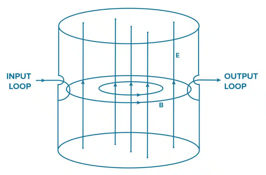
Standing waves are formed at particular frequencies and the cavity resonates at frequencies determined by the size and construction of the cavity. Conductors inserted into the cavity, as shown in Figure 1, allow for energy to be coupled into or out of the cavity.

To use cavity resonators as the building blocks of your filter, you can combine cavities of different characteristics to create the desired filter behavior.

A common type of cavity filter used today is the coaxial cavity filter, which consists of coupled TEM‐mode transmission lines, often metal posts, inside the cavity.

The transmission lines are typically shorted at one end and open on the other, with resonator lengths of less than λ/4. If the resonators are all aligned in the same direction, the filter is called a combline filter. If the resonators are alternating, the filer is called an interdigital filter.

When a Cavity Filter May Be Right for Your Application Needs

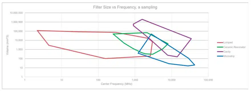
In general, cavity filters can be used in devices that operate up to 30GHz while offering high selectivity under high power. While cavity filters are often characterized as large in size, using innovative approaches to cavity construction, we can reduce the size of a cavity filter, making it quite similar to the size of a microstrip or ceramic resonator filter across various frequencies as shown in the graph in Figure 2.

Figure 2. Filter size versus frequency for different filter types Lumped, Ceramic, Cavity and Microstrip; source: Knowles Precision Devices

More specifically, for applications operating in the “X” band and above, until about 30 GHz, cavity combline filters can be made quite small, are easy to tune, easy to manufacture, and outperform lumped element options at these frequencies (lumped element designs are still an excellent option for lower frequencies). For operating frequencies above 30 GHz, the required dimensions become too small for a combline construction so we need to use either an interdigital cavity filter option for wide bands, which will cost more to develop, or waveguides for narrowbands.

Cavity Filter Options from Knowles Precision Devices

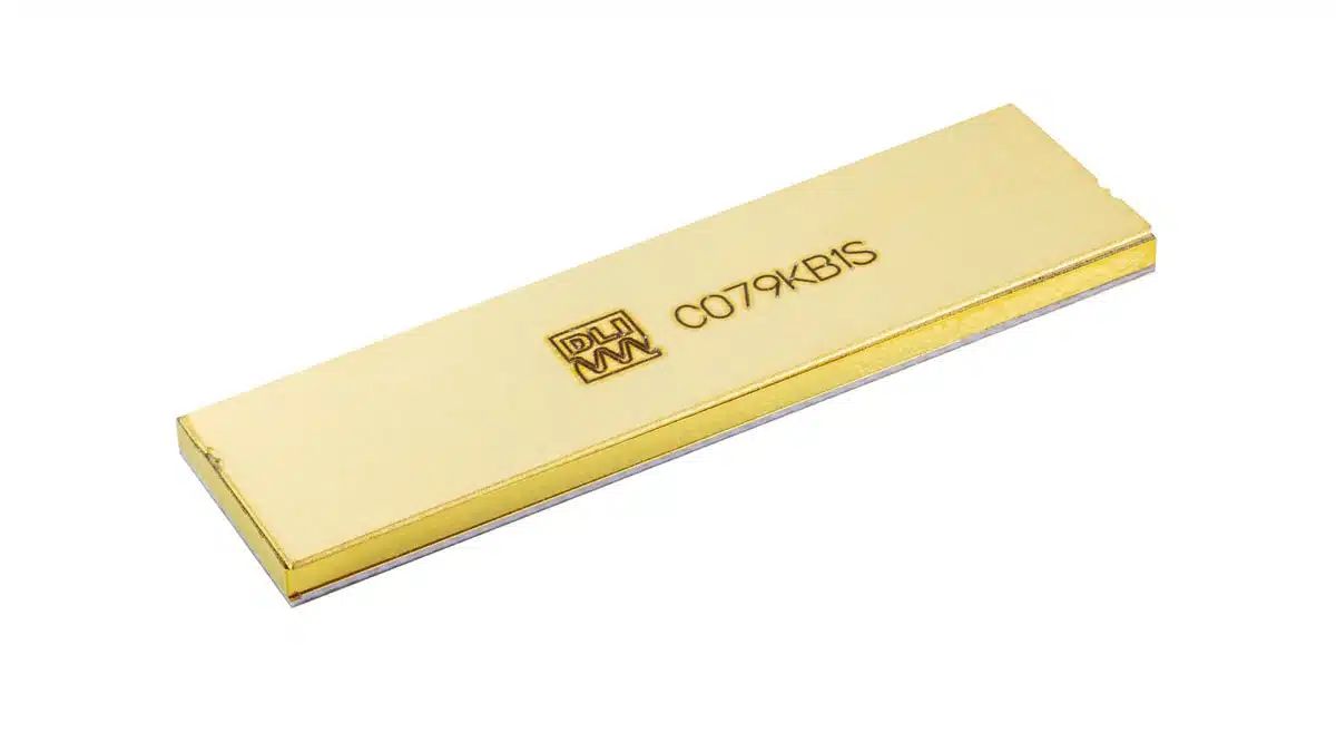
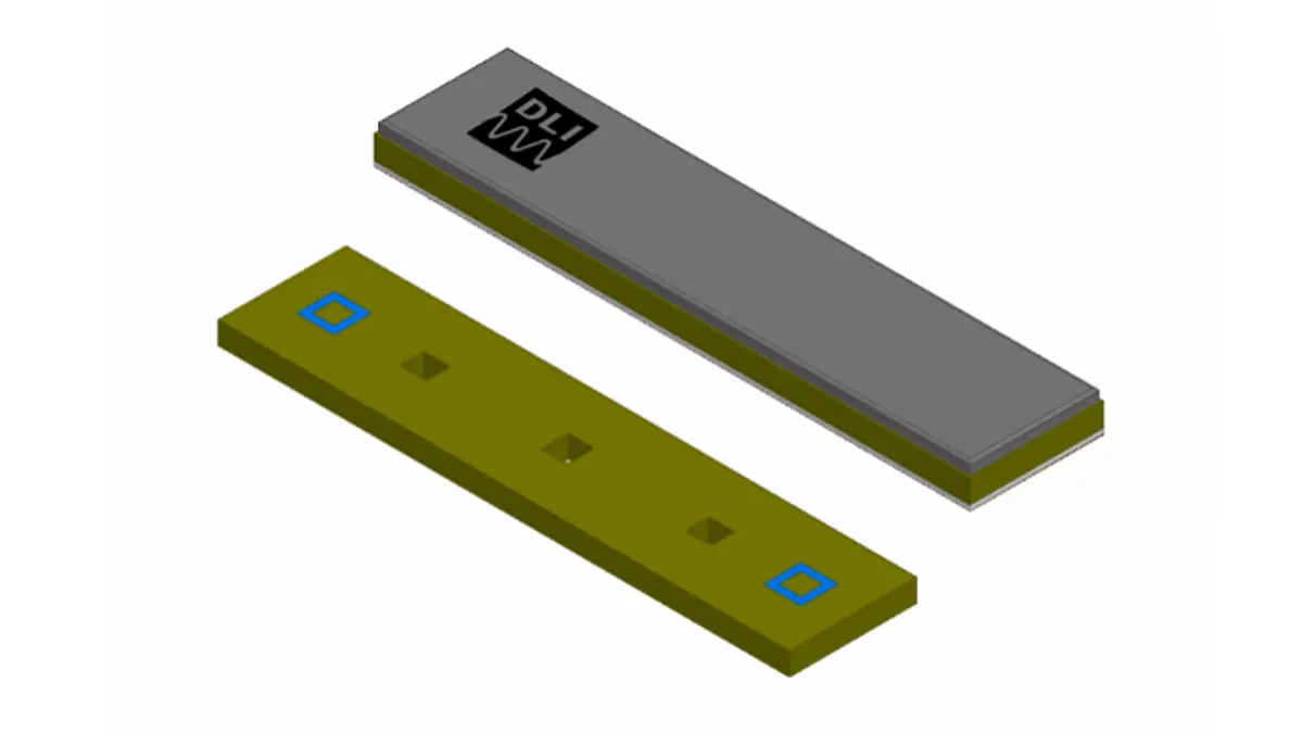
At Knowles Precision Devices, we use our stable, High Q ceramics to develop ceramic cavity low-loss bandpass filters that are small and have high selectivity. Our typical ceramic cavity filter is 30x smaller than filters designed using waveguide technology. With a multi-port implementation, we can create a very small, robust filter with wide reject band performance without spurious modes. The small shielded nature of our ceramic filter implementation makes it an ideal choice for integration in low noise receiver front ends with the antenna and pre-amplifier. Specs for our off-the-shelf ceramic cavity filters include the following:

  • 8 x 0.2 x 0.03 inch for 10 GHz filter
  • LO/Multiplier chains/RF pre-select/image filtering
  • Low loss in passband: 2-4 dB typical
  • Devices scalable from C to Ku band
  • Bandwidth 1 to 5 percent
  • Narrow footprints are great for switch filter banks
Cavity Filter Structure

We also make more traditional cavity filters in metal enclosures with the following specs:

  • Cavity bandpass for narrow to moderate bandwidths F0 = 200 to 30 GHz for bandpass filters 0.1 to 55 percent wide
  • Cavity band reject for narrow bandwidths F0 = 1000 MHz to 30 GHz 0.5 to 15 percent

Our design engineers are also available to work with customers to develop build-to-print or custom cavity filter options that meet your specific application needs. 

In general, our cavity filters are well suited for surface mount assembly and are ideal for high-power and high-reliability applications, such as those that may be required for devices used in space.

Related

Source: Knowles Precision Devices

Recent Posts

Standard vs Planar LLC transformers Comparison for Battery Chargers

13.3.2026
7

How Modern Tools Model Magnetic Components for Power Electronics

5.3.2026
46

Samtec ANSI/VITA 90 Connectors: Rugged Small Form Factor Standard

5.3.2026
10

Advanced Loss Modeling for Planar Magnetics in the Frenetic Planar Tool

4.3.2026
40

Mastering Galvanic Isolation in Power Electronics: Methods, Standards, and Implementation

2.3.2026
68

KYOCERA AVX Extends Ultra‑Broadband RF Capacitor Series

24.2.2026
51

Earthing Systems and IEC Classification Explained

26.2.2026
142

Kyocera Offers Small SAW Filters for IoT RF Modules

23.2.2026
20

Bourns Extends Multilayer Chip Inductors Offer for RF and Wireless Designs

20.2.2026
24

Upcoming Events

Mar 19
13:00 - 14:00 CDT

Smart Consideration of Inductor Thermal Performance

Mar 21
All day

PSMA Capacitor Workshop 2026

Apr 21
16:00 - 17:00 CEST

Heatsink Solutions: Thermal Management in electronic devices

View Calendar

Popular Posts

  • Buck Converter Design and Calculation

    0 shares
    Share 0 Tweet 0
  • Boost Converter Design and Calculation

    0 shares
    Share 0 Tweet 0
  • Flyback Converter Design and Calculation

    0 shares
    Share 0 Tweet 0
  • LLC Resonant Converter Design and Calculation

    0 shares
    Share 0 Tweet 0
  • MLCC Manufacturers Consider Price Increase as AI Demand Outpaces Supply

    0 shares
    Share 0 Tweet 0
  • Dual Active Bridge (DAB) Topology

    0 shares
    Share 0 Tweet 0
  • Ripple Current and its Effects on the Performance of Capacitors

    3 shares
    Share 3 Tweet 0
  • MLCC and Ceramic Capacitors

    0 shares
    Share 0 Tweet 0
  • MLCC Case Sizes Standards Explained

    0 shares
    Share 0 Tweet 0
  • 3-Phase EMI Filter Design, Simulation, Calculation and Test

    0 shares
    Share 0 Tweet 0

Newsletter Subscription


Passive Components Blog

© EPCI - Leading Passive Components Educational and Information Site

  • Home
  • Privacy Policy
  • EPCI Membership & Advertisement
  • About

No Result
View All Result
  • Home
  • Knowledge Blog
  • PCNS

© EPCI - Leading Passive Components Educational and Information Site

This website uses cookies. By continuing to use this website you are giving consent to cookies being used. Visit our Privacy and Cookie Policy.
Go to mobile version