


TT Electronics has announced that Hallogic OMH3075S Hall‑effect sensors from its Optek portfolio have been selected for integration into fan assemblies on the spacecraft, providing non‑contact motion sensing in a mission‑critical subsystem.
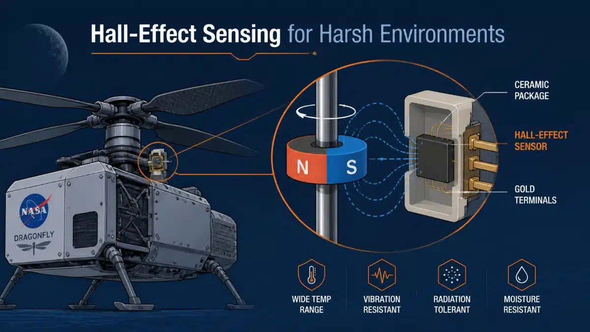
When NASA’s Dragonfly rotorcraft heads to Titan, even seemingly simple electromechanical subsystems, such as fans, need components that can operate reliably over a long mission in a very unfriendly environment.
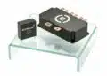
According to TT Electronics, the Dragonfly fan assemblies use Hallogic Hall‑effect devices to support a subsystem “where reliability and consistency are essential across the programme lifecycle.” The company identifies the Hallogic OMH3075S as a high‑reliability Hall‑effect sensor, designed for non‑contact switching and operation across a broad range of supply voltages. The device is specified for operation from −55 °C to +150 °C and is suitable for military and space applications, with variants processed and screened to MIL‑STD‑883 and an ESD rating of Class 3B per MIL‑STD‑883G, method 3015.7 (HB model).
The hall sensor at a glance
TT Electronics positions the OMH3075S as a high‑reliability Hallogic Hall‑effect sensor in a ceramic, side‑sensing through‑hole package. It is designed for non‑contact switching operations and is intended, among other things, for brushless DC motors, multiple‑pole magnets, assembly line automation, machine safety, and end‑of‑travel sensing. The same basic technology underpins its use in Dragonfly’s fan assemblies: the sensor monitors rotor or fan motion by detecting the magnetic field from an associated magnet, without physical contact.
Key parameters as published by TT Electronics and aligned distributor data are summarized in the table below.
| Parameter | Value / Range |
|---|---|
| Hall‑effect sensor type | High‑reliability Hallogic Hall‑effect sensor (bipolar latching) |
| Output type | Bipolar latching, open‑collector output |
| Supply voltage range V_CC | 4.5 V to 24 V |
| Max collector‑emitter voltage V_CE | 25 V |
| Operating point B_OP (min/typ/max) | 50 / 150 / 250 G |
| Release point B_RP (min/typ/max) | −250 / −150 / −50 G |
| Hysteresis B_HYS (min/typ/max) | 100 / 250–300 / 500 G (depending on source) |
| Operating temperature range | −55 °C to +150 °C (Hi‑Rel variants) |
| Package | Ceramic, side sensing, through‑hole |
| Lead length (min) | 0.40″ (10.16 mm) |
| Screening level (B, S versions) | Processed and screened to MIL‑STD‑883, space‑class |
| ESD rating | Class 3B per MIL‑STD‑883G, method 3015.7, HB model |
The broader Hallogic Hall‑effect sensor family incorporates a Hall element, linear amplifier, threshold amplifier, and Schmitt trigger on a single silicon chip, providing a logic‑level output with up to around 21 mA sink current and operation from 4.5 V to 24 V, according to TT Electronics and authorized distributors. This allows direct driving of multiple TTL loads or interface to standard logic families without extra buffering, which simplifies system‑level design.
Why these characteristics matter in fan and rotor applications
From a design‑engineering perspective, several aspects of OMH3075S are particularly relevant to fan assemblies and other rotating machinery.
First, the wide supply range of 4.5 V to 24 V provides flexibility when integrating into existing power architectures. The same sensor can sit on 5 V, 12 V or 24 V rails as commonly found in industrial or aerospace subsystems, reducing the need for dedicated regulators and simplifying reuse across platforms. TT’s specification of a maximum collector‑emitter voltage of 25 V and logic‑level open‑collector output is consistent with direct interface to a wide variety of digital or mixed‑signal control electronics.
Second, the bipolar latching magnetic behaviour, with defined operate and release points and a substantial hysteresis window, is advantageous in the presence of vibration and magnetic noise. TT specifies the operate point typically around 150 G and the release point around −150 G, with min/max ranges that extend from tens to a few hundred gauss for each. The 100–300+ G hysteresis band helps ensure that minor fluctuations in field due to mechanical run‑out, temperature‑dependent magnet strength, or external interference do not cause chatter at the output, which is especially important in speed and position feedback.
Third, the temperature capability and screening options map directly to harsh‑environment requirements. TT notes that OMH3075S is designed for operation from −55 °C to +150 °C and that B and S variants are processed and screened to MIL‑STD‑883 with an ESD rating of Class 3B. For a spacecraft subsystem or a high‑reliability industrial installation, such screening and temperature range make it possible to maintain consistent switching behaviour over long mission durations and under wide ambient variations.
Finally, the mechanical format contributes to robustness. TT specifies a ceramic side‑sensing package with a minimum 0.40″ lead length. The side‑sensing geometry allows the active area to be oriented toward a rotating magnet mounted on a shaft or fan hub, while the through‑hole leads support solid anchoring to the PCB and good mechanical stability under vibration.
Design considerations when using Hallogic‑type sensors
Although the Dragonfly application is extreme, many of the same design considerations will apply in more conventional equipment.
Magnet selection and placement is one of the first issues engineers face. TT’s published operate and release points provide the gauss levels that must be achieved at the sensor face for reliable switching, with hysteresis characterizing the required field change for toggling. When selecting a magnet and determining the air gap and alignment, designers can use these values as input to magnetic circuit simulations or empirical measurements, ensuring that in worst‑case conditions (temperature, tolerance stack‑up, ageing) the field at the Hall element still meets the minimum operate and release thresholds.
On the electrical side, the open‑collector output and logic‑level behaviour need appropriate biasing. TT’s Hallogic literature indicates that the family’s logic outputs can sink on the order of tens of milliamps, with up to around 21 mA cited for typical devices, and are intended to drive multiple TTL loads directly. In practice, this means choosing pull‑up resistors and interface circuitry that keep current within the specified limits at the chosen supply voltage and ensure that voltage levels at the controller inputs are compliant in both ON and OFF states.
Thermal and reliability requirements will drive the choice between standard and screened variants. For aerospace, defence, or other mission‑critical systems, TT’s B and S versions, which are processed and screened to MIL‑STD‑883 and specified for the full −55 °C to +150 °C operating range, provide a way to align the sensor with system‑level qualification goals. For less demanding environments, designers may decide that standard screening is sufficient, trading some qualification depth for cost or availability.
Finally, assembly and layout practices should consider both mechanical and EMC aspects. The 0.40″ minimum lead length and ceramic package allow some flexibility in positioning the active area relative to the board, which can be used to optimize distance to the magnet and mechanical isolation from vibration sources. At the same time, routing and decoupling around the Hall sensor’s supply and output should respect general best practices for mixed‑signal designs, especially in high‑dV/dt motor drive environments.
A concrete reference for harsh‑environment sensing
NASA’s selection of TT Electronics’ Hallogic OMH3075S Hall‑effect sensor for Dragonfly’s fan assemblies offers a useful reference design for engineers dealing with harsh environments, even if their own systems never leave Earth. The combination of wide supply range, bipolar latching behaviour with clearly defined magnetic thresholds, −55 °C to +150 °C operating range, MIL‑STD‑883 screening options, and a robust ceramic side‑sensing package illustrate what to look for when specifying motion and position sensors for long‑life, high‑reliability applications.
For readers who want to examine the device in more detail, TT Electronics provides a dedicated OMH3075S product page with key parameters and documentation, a combined datasheet for the OMH090/OMH3075/OMH3040 family, and additional Hallogic Hall‑effect sensor literature that expands on operating principles and application examples.
Source
This article is based on the manufacturer’s press release from TT Electronics and supported by official TT Electronics product and datasheet materials for the OMH3075S Hallogic Hall-effect sensor family.