


SCHURTER has introduced a new family of polymer PTC (PPTC) resettable fuses in both radial and SMD formats that target space‑constrained, high‑volume electronic designs.
The PFTA, PFTB, PFTC and PFTL series of SCHURTER PPTC resettable fuses provide automatic resettable protection against over-current and over-temperature events, helping designers improve reliability without the replacement effort associated with traditional fuses.
Key features and benefits
- Resettable overcurrent and overtemperature protection – The polymer PTC technology sharply increases resistance during a fault, limiting current and protecting downstream circuitry, then returns to a low‑resistance state once power is removed and the device cools.
- Current ratings from 0.05 A to 5 A – The family covers low‑current signal lines through to power rails in typical low‑ to medium‑power electronics, giving purchasing teams a unified source for multiple current ranges. Exact current ratings per type and size are according to the manufacturer datasheets.
- Voltage ratings up to 72 V – With maximum voltage ratings up to 72 V, the series addresses a wide range of DC applications, including battery packs and industrial control circuits that operate well above logic‑level voltages. Exact per‑part ratings should be confirmed in the respective datasheet.
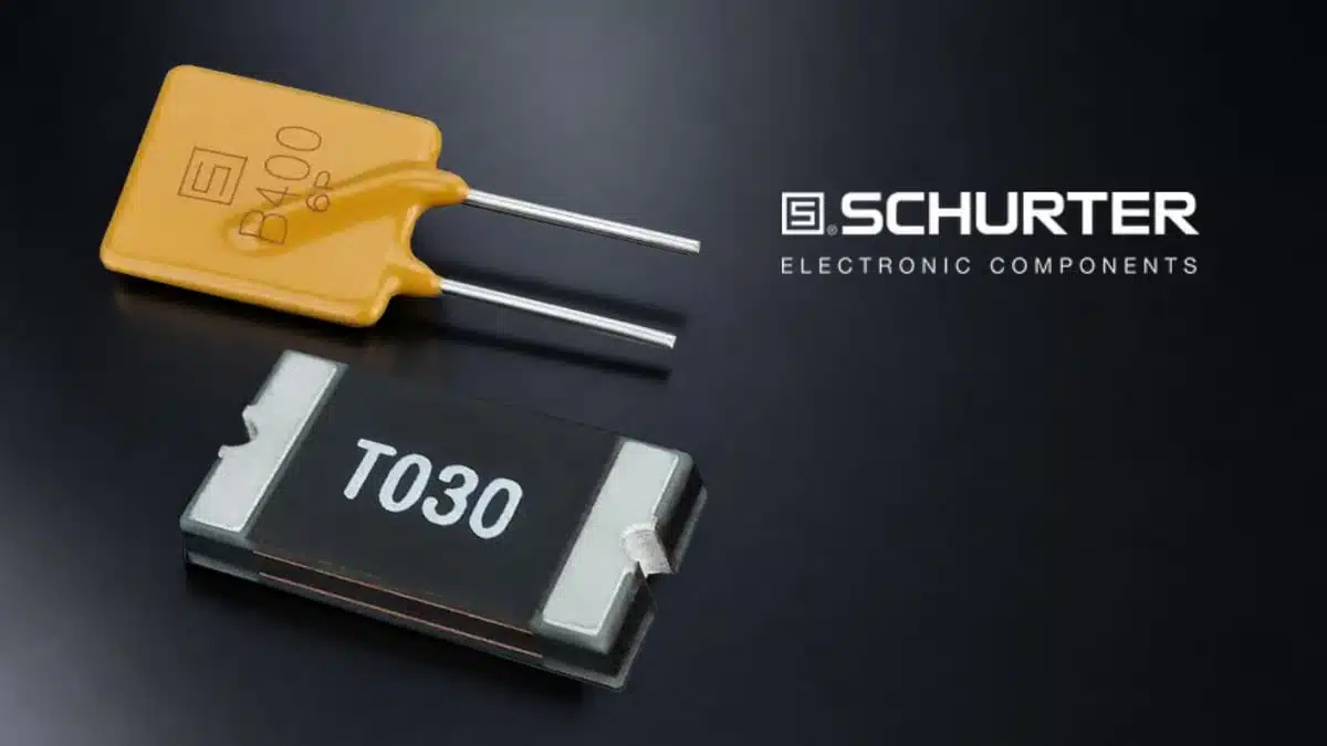
- Radial and SMD options – PFTA, PFTB and PFTC are designed for through‑hole (THT) assembly, while PFTL targets SMD assembly, supporting both traditional wave‑soldered boards and fully automated SMT production.
- Compact footprints for dense layouts – The particularly small PFTL SMD series enables high integration density in densely populated boards such as consumer devices, wearables and SSDs, where every square millimetre counts.
- UL‑compliant flame‑retardant materials – The use of UL‑compliant flame‑retardant materials supports compliance with international safety requirements and simplifies approval processes in end equipment.
- Designed for automated assembly – Package styles and terminations are compatible with standard automated assembly and soldering processes, an important factor for high‑volume industrial and consumer production.
Typical applications
SCHURTER positions the new PPTC range for a broad spectrum of markets where resettable overcurrent protection is preferred over one‑shot fuses.
- Energy storage systems and Li‑ion batteries – Protection of battery packs, battery management system (BMS) inputs and sense lines against shorts and overloads, with automatic reset after service or fault removal.
- Power supplies and adapters – Secondary‑side overcurrent protection in DC rails, auxiliary outputs and control circuits where downtime and manual fuse replacement are undesirable.
- Industrial electronics – I/O modules, sensor interfaces and control boards that may experience wiring faults, field mis‑wiring or intermittent shorts.
- Consumer electronics and wearables – USB ports, charging circuits, audio outputs and peripheral interfaces where compact protection and reset capability improve user experience and reduce returns.
- Automotive systems – Low‑voltage ECUs, infotainment modules and accessory lines that benefit from resettable overcurrent protection; actual suitability depends on individual series ratings and automotive qualification, which should be checked in the datasheets.
- Storage devices and SSDs – Protection of power rails and interface lines in solid‑state drives and similar storage products with high integration density.
Application mapping overview
The table below summarises typical roles for the new series in end equipment; exact limits are according to the manufacturer datasheets.
| Application area | Typical use of PPTC device |
|---|---|
| Battery packs / BMS | Line and pack protection against shorts/overload |
| DC power supplies | Secondary‑side rail and port protection |
| Industrial controllers | I/O and sensor line protection in field wiring |
| Consumer / wearables | USB, audio, small‑signal and charging port safety |
| SSDs / storage modules | Power and interface line protection on dense PCBs |
Technical highlights
Series scope and ratings
- Current range – Family coverage from 0.05 A up to 5 A supports both low‑current signal protection and higher‑current power lines; individual part numbers define the hold and trip currents for each package.
- Voltage range – Maximum operating voltages extend up to 72 V, allowing use in 12 V, 24 V, 48 V and similar DC systems, including many industrial and battery‑powered platforms.
- Form factors
- PFTA, PFTB, PFTC: Radial leaded devices for THT assembly, suitable for wave soldering and robust mechanical retention.
- PFTL: SMD series aimed at compact, fully automated SMT lines and high assembly density.
In practice, designers will choose the specific part based on parameters such as hold current, trip current, maximum voltage and time‑to‑trip characteristics, which are documented in the family datasheets.
Functional behaviour of SCHURTER PPTC devices
Polymeric PTC resettable fuses change resistance as a function of temperature and current.
- Under normal operating conditions, the conductive polymer remains in a low‑resistance state, and the device behaves like a small series resistor in the circuit.
- When a fault drives current above the trip threshold, internal heating causes a phase change in the polymer, leading to a sharp, nonlinear increase in resistance and thus limiting current to a small leakage level.
- The device stays latched in this high‑resistance state as long as the fault and applied voltage persist; once power is removed and the device cools, it returns to a low‑resistance state and the circuit can restart without component replacement.
For design engineers, this behaviour means that coordination between normal operating current, fault current and ambient temperature is essential to ensure both reliable protection and avoidance of nuisance tripping.
Availability and part numbers
The four main SCHURTER series, which are catalog products accessible via the SCHURTER website and distribution network include:
- PFTA series – Radial leaded PPTC devices covering a defined subset of the 0.05–5 A range; detailed electrical ratings, curves and mechanical dimensions are defined in the PFTA datasheet
- PFTB series – Radial leaded series with its own set of current and voltage combinations, allowing optimisation for specific applications or footprints.
- PFTC series – Another radial variant, typically differing in package size, resistance values or operating characteristics according to the datasheet.
- PFTL series – SMD PPTC devices aimed at compact layouts and automated SMT production, particularly where board area and height are constrained.
Exact ordering codes, packaging options (tape‑and‑reel, bulk, etc.), derating curves and agency approvals should be taken from the respective manufacturer datasheets linked from the press release.
Series overview
| Series | Mounting style | Typical use case focus |
|---|---|---|
| PFTA | Radial (THT) | General‑purpose board‑level protection |
| PFTB | Radial (THT) | Alternate footprints / ratings as required |
| PFTC | Radial (THT) | Additional rating/size options |
| PFTL | SMD | High‑density, fully automated SMT designs |
Design‑in notes for engineers
For engineers and component specifiers, PPTC devices require a methodical selection process to ensure reliable operation over the full life of the product.
- Start from normal operating current – Determine the maximum continuous current that the protected line will see in all operating modes, then select a PPTC with hold current at or above this value at the maximum ambient temperature.
- Check maximum voltage and fault current – Confirm that the device’s maximum rated voltage and maximum interrupt current exceed the highest voltage and likely fault current in the application to avoid damage or unsafe operation.
- Use Ihold/Itrip and derating tables – Consult the Ihold versus temperature curves and Itrip tables in the SCHURTER datasheets to verify that the device will not trip during normal operation, but will reliably trip for the defined fault scenario across the entire temperature range.
- Consider time‑to‑trip requirements – Some applications, such as power supplies or motor control, may require faster or slower trip behaviour; use the time‑to‑trip data to match the response time to system needs.
- Plan for reset behaviour and system restart – Because PPTC devices latch in a high‑resistance state until power is removed, system design should ensure that a fault triggers a proper shutdown or user intervention to allow the component to cool and reset.
- Layout and thermal aspects – For SMD PFTL devices used at higher currents, PCB copper area and thermal environment will influence operating temperature and, therefore, trip thresholds; layout guidelines from SCHURTER and empirical testing are advisable.
- Compliance and safety documentation – Where required by end‑product standards, make use of the UL and other safety approvals listed in the SCHURTER datasheets and catalog entries to support documentation and certification.
For purchasing and supply‑chain teams, consolidating on a single manufacturer’s PPTC portfolio can simplify sourcing and help maintain consistent protection behaviour across multiple product families, provided that each design is validated with the specific selected type.
Source
This article is based on SCHURTER’s official press release on the PFTA, PFTB, PFTC and PFTL PPTC series and the associated technical information provided on the manufacturer website and application notes.


